50W Build - Custom Layout

Get support and show off your MetroAmp 50 Watt kit builds.

Moderator: VelvetGeorge

Post Reply
TimK
New Member
Posts: 7
Joined: Thu Apr 28, 2011 8:39 am
Just the numbers in order: 7

50W Build - Custom Layout

Post by TimK » Tue Jul 05, 2011 3:48 pm

This being my first post, I would like to say hi to everyone. Like many I have been getting my fill of useful information here for some time before finally starting a project.

My goal is to create a single input version of the 1987 circuit which I can then use as a platform for modification, hopefully ending up with a second switchable channel based on a 2204 preamp with an extra gain-stage. But first thing's first...

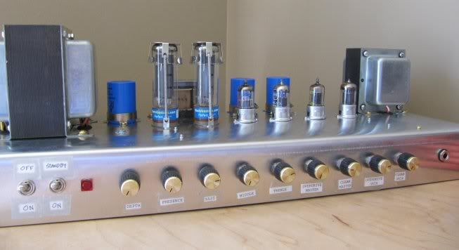
Having the benefit of an aluminum brake, I was able to fold my own chassis from .06 sheet aluminum. It didn't turn out that pretty, but I'll just say it has a nice hand-crafted vintage look. It's plenty sturdy enough and it think it will do the trick.

Image

Image

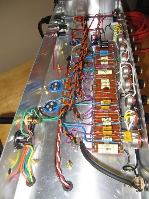
Since I will be drilling the chassis myself, I started playing around with the 1987 layout (as shown in the Metro instructions) to create something that might better suit my needs. I added a little Hiwatt influence by shortening the ptp board and adding a second board for the plate connections. I also relocated the OT to the other side of the chassis to free up space. You will also notice an extra 9-pin socket, extra pots, and empty space on the board for the anticipated gain stages.

Image
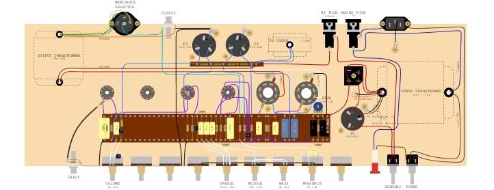
(Click picture to download high-res version)

Before I start drilling though, I figured it would best to ask a few questions and get whatever advice I can from here first. A few things that I'm wondering about:

1. In the Metro kit, the first filter can (F1) comes after the Standby switch. I have the filter cap right after the bridge rectifier, before the switch. To my knowledge this shouldn't make a difference and might in fact be a more correct way, but it doesn't hurt to ask.

2. For the heater wiring, I've aligned the tube sockets so that the heater wires will pass through horizontally in a straight line, being twisted above the rest of the connections to the tube sockets. I will connect the heaters to the V2 position, but no tube will be installed of course. What about the unused triode in V1? Does that need to be grounded or should I just leave it as is?

3. I have read that the preamp needs to ground in the same place as the preamp filter cap ground (F3). I have done this by running a wire from the pot grounding bus to the back of the chassis and onto the F3 grounding lug. Is this ok or should I ground to a closer point?

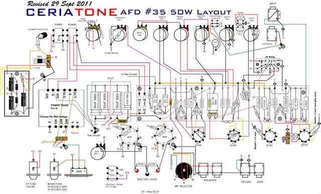
If you see any oversights I might have made or have any other advice for the layout it would be greatly appreciated. I'm fairly certain all the connections are correct, but I will be referencing the 1987 schematic and the Metro instructions during the build anyway.

Hopefully I don't catch too much flak for alter the traditional layout. :hide:
I look forward to sharing the rest of my build with the forum.
Attachments
50W-layout.zip
(976.72 KiB) Downloaded 730 times

User avatar
neikeel
Senior Member
Posts: 7231
Joined: Tue Dec 06, 2005 8:31 am
Location: Suffolk, England

Re: 50W Build - Custom Layout

Post by neikeel » Wed Jul 06, 2011 12:56 pm

Looks like a great project with plenty of flexibilty.

If there is no tube in the socket (until you put stuff in it) then it should not need grounding.

Wiring the first cap that way is fine, the metro only does it that way so you can use a SPST switch

The ground should go to the cap ground.
Neil

TimK
New Member
Posts: 7
Joined: Thu Apr 28, 2011 8:39 am
Just the numbers in order: 7

Re: 50W Build - Custom Layout

Post by TimK » Wed Jul 06, 2011 3:56 pm

The SPST standby switch should still work right the way I have it, correct? Only difference would be that since I have the standby switch between F1 and the rest of the plates, I will have to put the switch in the on position when draining the filter caps. Maybe I will just stick with the metro way to be safe.

As for grounding the unused tube, I realize V2 won't need grounding unless there is actually a valve installed. I am more worried about the second triode of V1 (V1b in the 1987 schematic). Since my build is only the bright channel of the circuit, the normal channel triode is unused even though the filaments are connected as usual. I found a discussion on this topic and it seems that it shouldn't matter. I will leave it floating as I intend to use it as separate gain stage at some point.

TimK
New Member
Posts: 7
Joined: Thu Apr 28, 2011 8:39 am
Just the numbers in order: 7

Re: 50W Build - Custom Layout

Post by TimK » Fri Jun 08, 2012 12:17 pm

Ok, I finally got around to putting this thing together. Here are some pics:

Image
Face-plates and head-cab will be made soon.

Image

Image

I really like the sound I'm getting. Right now it's sort of a Plexi bright channel and and a higher gain Bogner preamp. I hope to get sound clips up pretty soon but I'm just a sound engineer so have to find someone who can really play.

For those who are curious, I used Brian Wallace's 50W version of the Dagnall OT which I believe was only found in the 100W 2203's (?). I think the sound from this OT is just great, it really has that Van Halen thing going on. I've also used Brian's JMP50 PT and C1999 choke, Winged C EL34's, a NOS EI 12AX7 and Sozo vintage caps.

The heater wiring turned out to be a good move I think, however there is some hum/buzz when cranked. Overall though the SNR is fine for live/studio work (it is a guitar amp after all) but if anyone has any tricks to help my grounding please let me know. I tried grounding the heater CT at the same place as V1 (up by the input jack) but it made no difference.

So this brings me to the next step which is channel switching. I've got 4 VTL5C1 and I was thinking of doing something like the Soldano SLO, one LDR to shunt the unused channel to ground and one to decouple the unused master volume control. Looking at the SLO schematic it looks like I can just use the heater winding from the PT to power the LDR's but since it has to be rectified why not just go DC before the heaters and then power the LDR's after that? Will that even work ok? Which bridge rectifier should I use for this? I figured I would get some opinions before jumping in. If anyone has any ideas, please let me know.

Reeltarded
Senior Member
Posts: 512
Joined: Sat Aug 20, 2011 4:24 am
Just the numbers in order: 7

Re: 50W Build - Custom Layout

Post by Reeltarded » Sat Jun 09, 2012 5:27 am

Hey! Opinions? It's very cool! Please call it a Limo... it's a block long! ;)

Very cool! I would like to hear it when you get it done.
not kicking the dead horse

TimK
New Member
Posts: 7
Joined: Thu Apr 28, 2011 8:39 am
Just the numbers in order: 7

Re: 50W Build - Custom Layout

Post by TimK » Sat Jun 09, 2012 8:11 am

Hey thanks. I was actually looking for some people experience when it comes to channel switching, but that's ok. It's actually no bigger than the standard Plexi headcab. There's a lot of wasted space at the sides in that design.

User avatar
neikeel
Senior Member
Posts: 7231
Joined: Tue Dec 06, 2005 8:31 am
Location: Suffolk, England

Re: 50W Build - Custom Layout

Post by neikeel » Sat Jun 09, 2012 9:13 am

Take a look at this:

Image

That is a simple channel switcher with decicated 5v feed from the PT, does your PT have 5v (ie rectifier) taps, if so that PSU and switch would work. The 7805 will regulate the voltage at 5v so I am not sure if you could not use the heater taps at 6.3v and rely on the regulator for your switching circuit stabilty.

Other ideas here:http://forum.metroamp.com/viewtopic.php?f=4&t=35255
Neil

TimK
New Member
Posts: 7
Joined: Thu Apr 28, 2011 8:39 am
Just the numbers in order: 7

Re: 50W Build - Custom Layout

Post by TimK » Fri Jun 15, 2012 7:09 am

Unfortunately my PT does not have a dedicated 5v tap so I would have to use the heaters I think. I guess I could just build the SLO switching psu after the filaments and see if it powers the optocouplers. If any has done something like this or knows whether it will work or not please chime in.

Post Reply