Here's a '73 SuperLead that was modded all to hell by an amp guru in LA back in the late 80's. It sounds pretty good but the guy did really messy work. It would probably sound better stock with EL34's, at least for what I like, it's got 6550's in it now. I noticed among other things that the bias pot has a gob of goo on it preventing it from turning.
Here's what it sounds like in the studio with a '74 Les Paul and an older Marshall cab, real mikes (a 57 and a Neumann room mic) a real engineer and all:
from KIX Hotwire
Here's what is sounds like live with just a 57 jammed in the cone:
from KIX Live
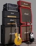
The guitar on the left playing the intros is this amp. Here's what it LOOKS like - Name that Mod!
Mark
Let's Play Name That Mod
Moderator: VelvetGeorge
-
FMmark

- Senior Member
- Posts: 84
- Joined: Tue Mar 29, 2005 10:52 pm
- Location: Northern VA
- Contact:
Let's Play Name That Mod
- Attachments
-
- ry-sl100-004.jpg
- (30.38 KiB) Downloaded 1567 times
-
- ry-sl100-003.jpg
- (35.46 KiB) Downloaded 1567 times
-
- ry-mod-sl-007.jpg
- (37.33 KiB) Downloaded 1567 times
-
Flames1950

- Senior Member
- Posts: 9294
- Joined: Sun Feb 08, 2004 1:04 am
- Location: Waukee, Iowa

-
FMmark
- Senior Member
- Posts: 84
- Joined: Tue Mar 29, 2005 10:52 pm
- Location: Northern VA
- Contact:
It's got some switches on the back that are interesting. A rotary switch for impedance selection, a switch labeled EL34 and 6550 and a switch for 50 or 100 watt. I suppose you can just pop out the 6550's and put in some EL34's and flip the switch, could it be that easy? Also the treble knob is a push-pull knob the kind with a side mounted pot so when you pull it out, it can attenuate. I never noticed it until I pulled the chassis out so I have no idea what it does yet. The mid knob is also push pull and has two thin wires connected to the board, never noticed that either.
Care to venture a guess what the gold resistor block at the far side of the chassis is doing? It is wired directly to the only working output jack, the other has idiot tape over it with a warning, obviously for the very dim roadie.
Care to venture a guess what the gold resistor block at the far side of the chassis is doing? It is wired directly to the only working output jack, the other has idiot tape over it with a warning, obviously for the very dim roadie.
"Ah my dear Watson, you see, but you do not observe." Sherlock Holmes
http://www.funnymoneyband.com
http://www.funnymoneyband.com
-
Billy Batz
- Senior Member
- Posts: 8566
- Joined: Fri Dec 10, 2004 8:49 pm
No. I strongly doubt it. Looking at the photo I can see the switch leading to the bias components and it looks like that switch simply changes the bias range to make it possible to put in 6550s AND EL34s and bias them correctly. You still have to bias whatever tubes you put in.FMmark wrote:I suppose you can just pop out the 6550's and put in some EL34's and flip the switch, could it be that easy? .
I have a few ideas but I cant see well enough to make a reall guess. If you can say what it does next time you play it I may get a better picture.Also the treble knob is a push-pull knob the kind with a side mounted pot so when you pull it out, it can attenuate. I never noticed it until I pulled the chassis out so I have no idea what it does yet.
Again I have some ideas but without a clearer shot or explanation of what it does its hard to guess.The mid knob is also push pull and has two thin wires connected to the board, never noticed that either.
Considering the size and being on the output signal theyre most likely some kind of attenuation or load device. It looks like its possible its activated by the jack's switch which may be why you dont get sound from one of them. If its just paralleled with the out jack then its attenuating some of the volume. Maybe it was supposed to be something that only works on the one jack.Care to venture a guess what the gold resistor block at the far side of the chassis is doing? It is wired directly to the only working output jack, the other has idiot tape over it with a warning, obviously for the very dim roadie.
Try and get some close ups of each of these things if you can. Its difficult to make out anything in those large shots. Leave them larger to if you can. It will ruin the page but we can see much better.
Last edited by Billy Batz on Thu Apr 07, 2005 5:29 pm, edited 1 time in total.
-
videocat23
- Senior Member
- Posts: 325
- Joined: Wed Sep 08, 2004 3:07 pm
- Location: Orlando, FL
- Contact:
i would agree that the big gold resistor is acting as in attenuator. maybe on the power supply, lowering the B+.
that's all i notice that I could pick out
that's all i notice that I could pick out
------------------------------------------
"Remember Bart, when participating in sporting events, it's not who wins or loses but how drunk you get..." Homer Simpson
"Remember Bart, when participating in sporting events, it's not who wins or loses but how drunk you get..." Homer Simpson
-
Billy Batz
- Senior Member
- Posts: 8566
- Joined: Fri Dec 10, 2004 8:49 pm
Now that I think of it I can tell you exactly what those resistors are probably for and why one jack doesnt work. There probably there in case the cord comes out to load the amp down. See when you plug into the one jack the resistors are wired to it cuts off those resistors with the switches on the jack. But when you plug into the other jack it doesnt switch them out so its loaded down and you get no sound.
-
Dax-The-Ax

- Senior Member
- Posts: 512
- Joined: Sun Dec 14, 2003 10:41 am
- Location: Tucson
-
VelvetGeorge

- Site Owner
- Posts: 7233
- Joined: Tue Oct 14, 2003 5:12 pm
- Just the numbers in order: 13492
- Location: The Murder Mitten
- Contact:

-
Dax-The-Ax
- Senior Member
- Posts: 512
- Joined: Sun Dec 14, 2003 10:41 am
- Location: Tucson
The cat's out of the bag!!! George, you're not suppose to tell anyone that you put that in there!!! I never do!!! I still have that FX Loop board you sent, i may let you turn her into a PTP Superlead Jewel with a tube buffered FX Loop!!! I love effects sometimes!!! It's a nice changeup once in a while!! George, maybe you could make a diagram so us Non-Schematic reading sissy bitches could think about a Tube FX Loop?
I lost the old pics, do you have one you could post? A pic With the Black & White Mystery Mod hider Goo!!!!????
I lost the old pics, do you have one you could post? A pic With the Black & White Mystery Mod hider Goo!!!!????
-
FMmark
- Senior Member
- Posts: 84
- Joined: Tue Mar 29, 2005 10:52 pm
- Location: Northern VA
- Contact:
Here's a couple more closeups. I'd love to know what those giant caps are supposed to give (or ruin) as well as the gold resistor block. The gold resistor block's blue and white wires are connected to the speaker output, it's a little easier to see in thses pics. Also the two push pull knobs that are wired to the board. Any ideas? (What a mess huh?)
- Attachments
-
- ry100resistor.jpg
- (42.52 KiB) Downloaded 1461 times
-
- ry100-003.jpg
- (47.38 KiB) Downloaded 1461 times
-
- ry100-001.jpg
- (49.65 KiB) Downloaded 1461 times
"Ah my dear Watson, you see, but you do not observe." Sherlock Holmes
http://www.funnymoneyband.com
http://www.funnymoneyband.com
-
VelvetGeorge
- Site Owner
- Posts: 7233
- Joined: Tue Oct 14, 2003 5:12 pm
- Just the numbers in order: 13492
- Location: The Murder Mitten
- Contact:
-
Billy Batz
- Senior Member
- Posts: 8566
- Joined: Fri Dec 10, 2004 8:49 pm
In the first pic that area where the two big orange drop caps were added and theres cable runing to and from those caps on the top and bottum thats part of the master volume. That would be very easy to reverse if you wanted to do that.
The swtich on the middle pot is doing something wierd. You can see that red/black wire pair running from the switch to the tone stack and were there is normally a slope resistor there is now what looks like two caps paralleled. I dont know what thats about. Maybe its shifting the range of the stack or something? Or DC blocked or soemthing?
I still cant really make out whats going on with the treble pot.
Those big caps are filter caps. There should be 6 cans on top of the chassis so if thats not the case maybe one of the filter can holes is used for something else and they just used axial caps inside the amp.
I still agree with my earlier assesment of the power resistors.
-
Guest
-
Billy Batz
- Senior Member
- Posts: 8566
- Joined: Fri Dec 10, 2004 8:49 pm
That is not the ****** mod. The ****** mod has nothing to do with the impedance selector. It puts a resistor accross the OT primaries. The single place to connect to the OT primaries is on pin 3 of each power tube. As it is those resistors are accross the secondaries. Otherwise known as a resistove load.
I just noticed another switch. The mini toggle to the left of the speaker jacks looks to be a half power switch which shuts off the 2 outer tubes.
I just noticed another switch. The mini toggle to the left of the speaker jacks looks to be a half power switch which shuts off the 2 outer tubes.