Soldano Hot Mod
Moderator: VelvetGeorge
-
- Senior Member
- Posts: 2120
- Joined: Wed Jun 09, 2004 8:19 pm
- Just the numbers in order: 7
Soldano Hot Mod
Can anyone explain a few things about this to me?
http://www.schematicheaven.com/newamps/ ... ot-mod.pdf
What is the symbol that is a straight bar like at the end of the 330k resistor? Is that ground?
Correct me if I am wrong, but looking at this schematic I would wire the 6k11 like this?
pin 1 on the tube to pin 9 on the 9 pin socket
pin 2 and 11 are tied together with a 200k resistor
pin 2 is tied to pin 6 on the socket, pin 5 to pin 6 on the socket via 2nf/1kv cap.
pin 3 to pin 8 on the socket
pin 4 to 2k7 resistor to (?)
pin 6 to pin 3 on the socket
pin 7 to pin 2 on the socket
pin 8 not used
pin 9 > 330k resistor wired in series to a 10nf/400V cap to pin 1 on the socket, this is junctioned with a 330k to (?) and at the pin 5 to pin 6 connection.
pin 10 & 11 on the tube are tied together
pin 12 to pin 4 on the socket, pins 4 & 5 on the socket are tied together.
Pins 1 & 12 on the tube are internally tied together?
Ok now here is the question.... Where would one find a housing to encapsulate this componants while having a male 9 pin socket and a female 12 pin socket? I guess an easy way would be to create my own box, but would this be feasible?
Something like this perhaps? http://www.apexelectronic.com/connectors.htm scroll down to the 9 pin tube style Connector and modify it to accept the componants as well as another type of adapter to seat the 12 pin socket to?
Actually the picture of one of these looks cheapo
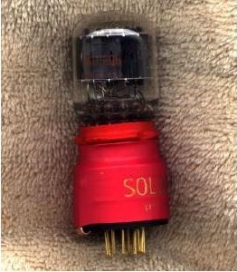
The tube is shrink wrapped to the 9 pin socket, this is evan easier now come to think about it.
Last edited by Necrovore on Wed Dec 13, 2006 2:14 pm, edited 1 time in total.
- novosibir
- Senior Member
- Posts: 4654
- Joined: Tue Nov 22, 2005 2:32 pm
- Just the numbers in order: 7
- Location: Nuernberg, Germany
- Contact:
The link doesn't work!
Larry
Larry
The fault almost always is sitting in front of the amp
Larry's Website now with included Pix's Gallery
- novosibir
- Senior Member
- Posts: 4654
- Joined: Tue Nov 22, 2005 2:32 pm
- Just the numbers in order: 7
- Location: Nuernberg, Germany
- Contact:
I've had the same part. Useful to make a hiss machine out of a MarshallMacGaden wrote:Mine was a plain brass tube, with pins at the bottom, and a socket on top for the new tube. The components were encapsulated inside the brass tube in clear epoxy. Now THAT looked cheap !
Larry
The fault almost always is sitting in front of the amp
Larry's Website now with included Pix's Gallery
- novosibir
- Senior Member
- Posts: 4654
- Joined: Tue Nov 22, 2005 2:32 pm
- Just the numbers in order: 7
- Location: Nuernberg, Germany
- Contact:
Re: Soldano Hot Mod
Yep! Ground!Necrovore wrote:What is the symbol that is a straight bar like at the end of the 330k resistor? Is that ground?
Larry
The fault almost always is sitting in front of the amp
Larry's Website now with included Pix's Gallery
-
- Senior Member
- Posts: 2120
- Joined: Wed Jun 09, 2004 8:19 pm
- Just the numbers in order: 7
Re: Soldano Hot Mod
Ok.... In a case like this, how and where exactly would you ground this thing? To the brass tube?novosibir wrote:Yep! Ground!Necrovore wrote:What is the symbol that is a straight bar like at the end of the 330k resistor? Is that ground?
Larry
-
- New Member
- Posts: 17
- Joined: Sat Apr 23, 2005 8:37 pm
- Location: Upstate NY
- Contact:
-
- New Member
- Posts: 43
- Joined: Thu Sep 28, 2006 3:41 pm
- Just the numbers in order: 7
- Location: Solderhell
The Hot Mod would get the ground by the 9 pin 12ax7 socket. The hot mods were notorious for cutting in and out due to this ground. I had a few of them. One didn't have the flat copper ground, instead it was like a giant solder wick Some Marshall's 12ax7 sockets were just riveted to the chassis and made a piss poor ground. I use to solder a wire to the Hot Mod ground then a ground lug on the other end and directly secured to the chassis. Never had problems with it cutting out again. The hiss factor was another issue all together
- mr coffee
- Senior Member
- Posts: 58
- Joined: Fri May 11, 2007 8:35 pm
I've used them in bandmaster/bassman heads
back in the day...when I was running emg pickups.....piles of effects
- roberto
- Senior Member
- Posts: 59
- Joined: Mon May 05, 2008 9:44 am
Re: Soldano Hot Mod
look at the picture, on the left, near pins, you'll see the ground connection.Necrovore wrote:How and where exactly would you ground this thing? To the brass tube?
should be better to use a REAL ground.
-
- New Member
- Posts: 30
- Joined: Sun Nov 22, 2009 1:20 am
- Just the numbers in order: 7
Re: Soldano Hot Mod
Hi all
I know this is a very old topic....but I would like to reopen it a bit .
I would like to DIY the HM. The schematic on schem heaven is really clear so I believe I would be able to make a try.
The only concern I have with the layout is the 2 x 330K resistors. They are not layout as a voltage divider. Is this normal?
Is this a mistake on the drawing?
At the moment the signal is going from the plate to the 10nf cap to a 330k res an then to the grip of the next tube. The second 330K res is connected at the junction of the cap and res above and the other end of the second resistor is connect to ground.
Thanks for your help
-
- New Member
- Posts: 1
- Joined: Thu Dec 07, 2017 3:29 pm
- Just the numbers in order: 13492
Re: Soldano Hot Mod
Has anyone built one yet? I ordered the 6k11 tube and have a schematic. Entered the schematic into multisim and it just oscillates at around 300 hz so there's clearly an error in the diagram. Also the person in charge of producing them has said himself there were errors on that schematic, but didn't specify what...