Here's the link. JCM800 in small combo cabinet. Some vintage stuff, some new stuff, custom plates, etc. Great to be back!
http://joepopp.net/jcm800combo/
Doing a new build for the first time in 5 years!
-
Joe Popp

- Senior Member
- Posts: 302
- Joined: Tue May 29, 2007 9:13 pm
-
young flower
- Senior Member
- Posts: 119
- Joined: Sun Mar 04, 2012 7:38 pm
- Just the numbers in order: 13492
- Location: Austria, Vienna
Re: Doing a new build for the first time in 5 years!
Wow - great attention to detail - very OCD  . And a really nice blog. I´m sure this is going to be a great build
  . Thanks for sharing!
-
neikeel

- Senior Member
- Posts: 7231
- Joined: Tue Dec 06, 2005 8:31 am
- Location: Suffolk, England
Re: Doing a new build for the first time in 5 years!
Hi Joe
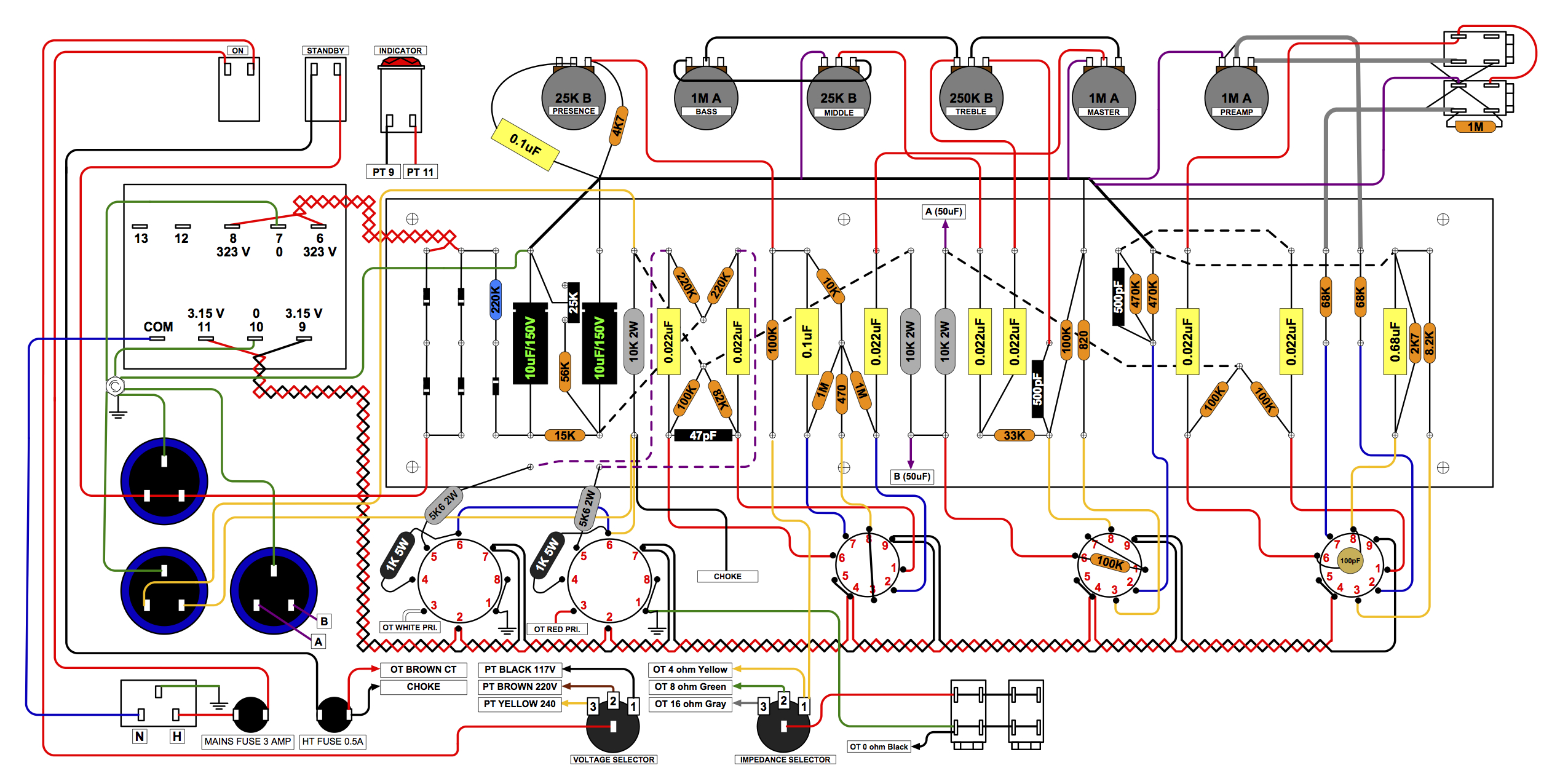
I tried to leave a comment about making sure the HT feed for your bias circuit MUST NOT be wired the way your diagram shows. The bias needs to be fed direct off your PT. Either off the PT lug or from the hot side of the standby switch.
Your amp needs to see bias voltage before you throw the HT at the diodes.
Neil
-
Joe Popp
- Senior Member
- Posts: 302
- Joined: Tue May 29, 2007 9:13 pm
Re: Doing a new build for the first time in 5 years!
Neil, I really appreciate you looking man! The drawing is not final. I've already made some corrections. I'm going off Nik's latest layout on the Ceriatone site. I will look it over again. Thanks again, you and so many others have been a great help on here over the years.
-
demonufo

- Senior Member
- Posts: 3882
- Joined: Thu Dec 13, 2007 8:36 am
- Just the numbers in order: 13492
- Location: Carterton, Oxon, U.K.
- Contact:
Re: Doing a new build for the first time in 5 years!
Has it really been 5 whole years since the last one? Crikey! 
Still, I knew you wouldn't be able to stay away from a Master MkII circuit for too long.
Glad to see you're still around these parts.
Oh and, good catch Neil.
Lots of flaws on that BillyBatz metro layout, but still my favourite of those widely available. Obvious missing wires on tonestack (treble pot), missing NFB lead, bias wiring as mentioned, and missing link lead on the input jacks. Also, better off mounting the 68K show on the jacks directly to the tube socket and using shielded wire, grounded at the jacks. Shielded cable on V1a from gain pot to grid may also be of benefit, but in certain environments, the shielded V1b can be essential. Especially since you have lowered V1a cathode to 8K2.
Nice work, as usual, Joe. Keep it up.
So I like purple, okay!!!!!!
83.7% of all statistics are made up on the spot!
83.7% of all statistics are made up on the spot!
-
Joe Popp
- Senior Member
- Posts: 302
- Joined: Tue May 29, 2007 9:13 pm
Re: Doing a new build for the first time in 5 years!
Neil and Demonufo:
Thanks again for your input!
Neil:
Here is the basic layout I am using. The only main difference is that I will be using an off board bias pot ala Komet style:
http://www.joepopp.net/jcmtwins/jcmtwins003big.jpg" onclick="window.open(this.href);return false;
My original design was based off of the March 2007 Ceriatone layout. I have built 4 amps this way and the bias circuit works. That doesn't mean it is the best way.Doesn't the jumper between the 220K and the diode serve the same purpose of coming off of the standby lug? The Metroamp layout uses the lug basically as a jumper. Again, I could be mistaken. I am a builder and not a tech. I am the first guy to admit that!
http://www.joepopp.net/jcm800layouts_07 ... .12.07.jpg" onclick="window.open(this.href);return false;
Here is the layout from the metroamp Wiki:
http://www.metroamp.com/downloads/2204_50W_MV.pdf" onclick="window.open(this.href);return false;
I see that Nik has changed some things around on this new layout:
http://www.ceriatone.com/images/layoutP ... iatone.jpg" onclick="window.open(this.href);return false;
I want to use the BEST way and most Marshally way. Any advice appreciated!
-
Joe Popp
- Senior Member
- Posts: 302
- Joined: Tue May 29, 2007 9:13 pm
Re: Doing a new build for the first time in 5 years!
demonufo wrote:Has it really been 5 whole years since the last one? Crikey!
Also, better off mounting the 68K show on the jacks directly to the tube socket and using shielded wire, grounded at the jacks. Shielded cable on V1a from gain pot to grid may also be of benefit, but in certain environments, the shielded V1b can be essential. Especially since you have lowered V1a cathode to 8K2.
Nice work, as usual, Joe. Keep it up.
Thanks for this! I will incorporate this advice into the build. Some show the 68K right on the input jack. I never had any trouble with mine being on the board but I saw the other thread and a guy using my website had problems.
THANKS MAN!
-
Haze13
- Senior Member
- Posts: 413
- Joined: Tue Oct 16, 2012 10:33 am
- Just the numbers in order: 13492
- Location: Israel. Bat-Yam
Re: Doing a new build for the first time in 5 years!
Hi Joe
I am the guy who had the these problems, but I don't think that there is a problem with your layout. I live in the old house, and and all of the electrical wiring in the house looks like a rat nest. I can hear my washing machine through the amp, and used to pick the radio with the wah pedal, before I shielded long wires in there.
I think that for you, as playing musician, is better to use every precaution when building an amp, because you can't be sure on 100% that the place where you'll be playing has no problems with electrical wiring, ground loops, radio and etc...
I have a topic about noise problems that I had, may be it will help you.
http://forum.metroamp.com/viewtopic.php?f=7&t=40935
One of the ways there is really Marshally! Like a sheet of metal on the bottom of a head cab...
-
neikeel
- Senior Member
- Posts: 7231
- Joined: Tue Dec 06, 2005 8:31 am
- Location: Suffolk, England
Re: Doing a new build for the first time in 5 years!
Both the layouts are wrong!
The metro one should have the bias feed coming off the other side of the standby switch. Wonder how that diagram escaped quality control>
The metro one should have the bias feed coming off the other side of the standby switch. Wonder how that diagram escaped quality control>
Neil
-
Joe Popp
- Senior Member
- Posts: 302
- Joined: Tue May 29, 2007 9:13 pm
Re: Doing a new build for the first time in 5 years!
Neil:
Here is another layout from Triode that has the bias wired the same as mine. Not understanding why it won't work. Will the amp not bias correctly? Is it dangerous? I certainly want it to be right! Thanks again.
http://site.triodestore.com/JCM8002204Stock.pdf" onclick="window.open(this.href);return false;
-
neikeel
- Senior Member
- Posts: 7231
- Joined: Tue Dec 06, 2005 8:31 am
- Location: Suffolk, England
Re: Doing a new build for the first time in 5 years!
If you look at the triode store one it is slightly different. The HT ac from the PT is fed directly to the diodes and see voltage/current/juice WHY as soon as you flick the mains switch. The standby switch is down stream of the rectifier diodes and switches the dc line after the mains filter cans but before the choke and screens connection on the HT fuse holder (trace it out for yourself).
Here it is in schematic form:http://marstran.com/10513%201987.gif
So many early 70s Marshalls killed their PTs due to this wiring design error (rare to see the late 60s ones with laydown PTs fail as they were wired correctly).
The bias circuit and therefore the output tubes need to be powered up whilst on standby so that when you hit them with B+ they are up to speed!
Have a read around the subject there are plenty of warnings on how to avoid frying a new PT on this era of JMP50
Neil
-
demonufo
- Senior Member
- Posts: 3882
- Joined: Thu Dec 13, 2007 8:36 am
- Just the numbers in order: 13492
- Location: Carterton, Oxon, U.K.
- Contact:
Re: Doing a new build for the first time in 5 years!
The triode and the ceriatone ones are correct in that the bias circuit is constant and you won't get a massive surge when you flip standby. However, Marshall did it from the standby switch (electrically it is the same).
But NOT like the metro layout, as the bias circuit is not in play until you flip the standby switch. Many 70's 50W amps were wired this way. This is why you don't see many 50Watters of that era with the original PT intact.
So Marshall, would be like the metro layout, but wired from the TOP of the standby, direct to the HT tap from the PT, rather than from the switched side of the standby.
Also, it should be mentioned, if you ARE using shielded grids on V1, you can omit the cap across the V1 socket, as this will not do anything further to reduce parasitic oscillation, but will tone down the high end further. Only the later horizontal input amps actually had this cap, and no shielded cable, where as the earlier ones either had shielded cable, or very careful lead dress.
EDIT: The Doc. beat me to it.
But NOT like the metro layout, as the bias circuit is not in play until you flip the standby switch. Many 70's 50W amps were wired this way. This is why you don't see many 50Watters of that era with the original PT intact.
So Marshall, would be like the metro layout, but wired from the TOP of the standby, direct to the HT tap from the PT, rather than from the switched side of the standby.
Also, it should be mentioned, if you ARE using shielded grids on V1, you can omit the cap across the V1 socket, as this will not do anything further to reduce parasitic oscillation, but will tone down the high end further. Only the later horizontal input amps actually had this cap, and no shielded cable, where as the earlier ones either had shielded cable, or very careful lead dress.
EDIT:
So I like purple, okay!!!!!!
83.7% of all statistics are made up on the spot!
83.7% of all statistics are made up on the spot!
-
Joe Popp
- Senior Member
- Posts: 302
- Joined: Tue May 29, 2007 9:13 pm
Re: Doing a new build for the first time in 5 years!
Neil and Demonufo,
Thanks guys! But I am not understanding. My standby switch is wired the same as the Triode layout.
HT Fuse > Standby switch > Positive cap can lugs > Bottom left diode
The PT Connects to the top two diodes, which I also have the same.
Is there a 2204 Layout that has this section drawn correctly as you describe?
I don't want to bug you guys, I will surf around. I am still a long way from wiring this up!
-
neikeel
- Senior Member
- Posts: 7231
- Joined: Tue Dec 06, 2005 8:31 am
- Location: Suffolk, England
Re: Doing a new build for the first time in 5 years!
Actually your top layout is ok with switch in the HT dc line. This is hard on your standby switch which would be better with two poles switching ac pre rectifier (like a modified version of the Metro one - just moving the white wire to the other lugs of the DP switch.
Neil