From Scratch Amp Building Chronicle - 6/13/10 UPDATED!!
- sah5150
- Senior Member
- Posts: 477
- Joined: Thu Aug 02, 2007 5:32 pm
- Location: Obviously, you're not a golfer!
Re: From Scratch Amp Building Chronicle - 12/25/09 UPDATED!!
New layout that incorporates different relays and some updates for correct size components. I realized I could not use the relays I originally chose because I could not mount them on the board the way I wanted due to the fact that the legs of the relays were too close together. I've now gone with 6V Panasonic relays that have a 16 pin pitch instead of the Omrons I had planned to use, which only have a 12 pin pitch...
New layout with multiple fixes
Steve
New layout with multiple fixes
Steve
Henning Amplification Website - http://www.henningamps.com
My Music Page (Mojave PeaceMaker, Axe-FX, Mesa MKIV and PODXT Pro Clips)
My Music Page (Mojave PeaceMaker, Axe-FX, Mesa MKIV and PODXT Pro Clips)
- sah5150
- Senior Member
- Posts: 477
- Joined: Thu Aug 02, 2007 5:32 pm
- Location: Obviously, you're not a golfer!
Re: From Scratch Amp Building Chronicle - 1/10/10 UPDATED!!
Drilling and Staking my custom board
So... today I needed to build my custom board. I have a nice piece of red swirl board material that is 3.125" x 16" - exactly what I need for my board. The first thing I did was print out a life size template of my board showing where the eyelets needed to be placed. I'm using two sizes of eyelets for this board - 1/8" and 3/32" for the relay sockets and the LDR. I needed to cut 3 size holes - 1/8", 3/32" and 9/64" for the posts to hold the board in the amp. I assembled the bits I needed, taped the template to the board the best I could, clamped the board into my drill press and started drilling:


Here is the fully drilled board. It is not perfect by any means, but for the prototype it will work fine. The production amps I'll have a template made so everything is absolutely perfect:

Now it is time to start staking the eyelets. I chose to use eyelets rather than turrets because I just think it looks cleaner, especially since the relays really required eyelets. First, you stake the 3/32 eyelets since they are smaller and you need to have them flat to the board when staking. First, I put in all the 3/32 eyelets:

Just a quick test to make sure the relay sockets fit. And they do!:

Now, tape the eyelets in using electrical tape so they don't fall out when you turn the board over to stake it. Make sure they are flat to the top of the board!:

Now use the pointy end of the staking tool in the drill press to stake the eyelets. You're not turning on the press, just using a bit of force the spread the bottom of the eyelets so they stay in nice and tight. You don't need to press hard at all:

And now do the same thing for the 1/8" eyelets. Here is a picture of the finished board ready for components. We're humming along now!:


Steve
So... today I needed to build my custom board. I have a nice piece of red swirl board material that is 3.125" x 16" - exactly what I need for my board. The first thing I did was print out a life size template of my board showing where the eyelets needed to be placed. I'm using two sizes of eyelets for this board - 1/8" and 3/32" for the relay sockets and the LDR. I needed to cut 3 size holes - 1/8", 3/32" and 9/64" for the posts to hold the board in the amp. I assembled the bits I needed, taped the template to the board the best I could, clamped the board into my drill press and started drilling:


Here is the fully drilled board. It is not perfect by any means, but for the prototype it will work fine. The production amps I'll have a template made so everything is absolutely perfect:

Now it is time to start staking the eyelets. I chose to use eyelets rather than turrets because I just think it looks cleaner, especially since the relays really required eyelets. First, you stake the 3/32 eyelets since they are smaller and you need to have them flat to the board when staking. First, I put in all the 3/32 eyelets:

Just a quick test to make sure the relay sockets fit. And they do!:

Now, tape the eyelets in using electrical tape so they don't fall out when you turn the board over to stake it. Make sure they are flat to the top of the board!:

Now use the pointy end of the staking tool in the drill press to stake the eyelets. You're not turning on the press, just using a bit of force the spread the bottom of the eyelets so they stay in nice and tight. You don't need to press hard at all:

And now do the same thing for the 1/8" eyelets. Here is a picture of the finished board ready for components. We're humming along now!:


Steve
Last edited by sah5150 on Sun Jan 10, 2010 8:21 pm, edited 1 time in total.
Henning Amplification Website - http://www.henningamps.com
My Music Page (Mojave PeaceMaker, Axe-FX, Mesa MKIV and PODXT Pro Clips)
My Music Page (Mojave PeaceMaker, Axe-FX, Mesa MKIV and PODXT Pro Clips)
-
paulster
- Senior Member
- Posts: 620
- Joined: Mon Mar 13, 2006 4:25 pm
- Just the numbers in order: 7
- Location: Los Angeles & London
Re: From Scratch Amp Building Chronicle - 12/27/09 UPDATED!!
Nice IC socket technique, Steve! 
The build's looking really good.
The build's looking really good.
- sah5150
- Senior Member
- Posts: 477
- Joined: Thu Aug 02, 2007 5:32 pm
- Location: Obviously, you're not a golfer!
Re: From Scratch Amp Building Chronicle - 12/27/09 UPDATED!!
Yes, and allow me to thank paulster publicly here for hipping me to this! You might notice that I changed relays so that I could get one with a 16 pin pitch. The Omrons I had planned to use are only 12 pin pitch, so the pins were too close together to mount this way. I was able to use 3/32" eyelets for the relays with this build. I think it is a good choice because it allows me a bit more room for the many wires running from the relays than the 1/16" you use for the relays. I used 1/8" for the diodes because there are a lot of wires running from those as well....paulster wrote:Nice IC socket technique, Steve!
Thanks man!paulster wrote:The build's looking really good.
Steve
Henning Amplification Website - http://www.henningamps.com
My Music Page (Mojave PeaceMaker, Axe-FX, Mesa MKIV and PODXT Pro Clips)
My Music Page (Mojave PeaceMaker, Axe-FX, Mesa MKIV and PODXT Pro Clips)
- joey
- Senior Member
- Posts: 982
- Joined: Thu Aug 20, 2009 10:40 pm
- Just the numbers in order: 7
- Location: Allston, Massachusetts
- sah5150
- Senior Member
- Posts: 477
- Joined: Thu Aug 02, 2007 5:32 pm
- Location: Obviously, you're not a golfer!
Re: From Scratch Amp Building Chronicle - 12/27/09 UPDATED!!
More progress on the board:
Wiring the under board connections. Used 22 AWG buss wire and covered with the black tubing:

Top of the board - soldered a few components on the far end of the board to get used to working with the eyelets:

Working in some more components. You can see I'm using 22 AWG teflon coated wire - kick ass! Won't melt when the iron hits it! Solen and BC caps, Riken and PRP resistors...

Steve
Wiring the under board connections. Used 22 AWG buss wire and covered with the black tubing:

Top of the board - soldered a few components on the far end of the board to get used to working with the eyelets:

Working in some more components. You can see I'm using 22 AWG teflon coated wire - kick ass! Won't melt when the iron hits it! Solen and BC caps, Riken and PRP resistors...

Steve
Henning Amplification Website - http://www.henningamps.com
My Music Page (Mojave PeaceMaker, Axe-FX, Mesa MKIV and PODXT Pro Clips)
My Music Page (Mojave PeaceMaker, Axe-FX, Mesa MKIV and PODXT Pro Clips)
-
xbearxau
Re: From Scratch Amp Building Chronicle - 12/30/09 UPDATED!!
Looking great Steve. You do realise you started this thread in March 09? Its coming up to a birthday so get assembling 
- sah5150
- Senior Member
- Posts: 477
- Joined: Thu Aug 02, 2007 5:32 pm
- Location: Obviously, you're not a golfer!
Re: From Scratch Amp Building Chronicle - 12/30/09 UPDATED!!
I know, I'm goddamn slow!!!xbearxau wrote:Looking great Steve. You do realise you started this thread in March 09? Its coming up to a birthday so get assembling
Steve
Henning Amplification Website - http://www.henningamps.com
My Music Page (Mojave PeaceMaker, Axe-FX, Mesa MKIV and PODXT Pro Clips)
My Music Page (Mojave PeaceMaker, Axe-FX, Mesa MKIV and PODXT Pro Clips)
- sah5150
- Senior Member
- Posts: 477
- Joined: Thu Aug 02, 2007 5:32 pm
- Location: Obviously, you're not a golfer!
Re: From Scratch Amp Building Chronicle - 1/10/10 UPDATED!!
Some more progress:
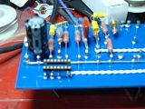
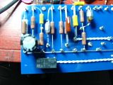
This is the back end of the board. I soldered in a 16 pin DIL Socket that had the pins removed that the relay didn't use. As you can see, I've inserted the relay in the socket now. I also soldered in all the wires I needed from the relay to the controls. You can see the flyback suppression diode at the front :

Here's a couple more views:


Here is the front end of the board - first two gain stages. Not quite done:

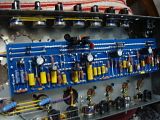
Here is the whole board as it stands now:

Steve
This is the back end of the board. I soldered in a 16 pin DIL Socket that had the pins removed that the relay didn't use. As you can see, I've inserted the relay in the socket now. I also soldered in all the wires I needed from the relay to the controls. You can see the flyback suppression diode at the front :

Here's a couple more views:


Here is the front end of the board - first two gain stages. Not quite done:

Here is the whole board as it stands now:

Steve
Henning Amplification Website - http://www.henningamps.com
My Music Page (Mojave PeaceMaker, Axe-FX, Mesa MKIV and PODXT Pro Clips)
My Music Page (Mojave PeaceMaker, Axe-FX, Mesa MKIV and PODXT Pro Clips)
-
screamindemon
- New Member
- Posts: 21
- Joined: Tue Jan 12, 2010 3:53 pm
- Just the numbers in order: 7
Re: From Scratch Amp Building Chronicle - 1/10/10 UPDATED!!
Awesome build. Can't wait to here it.
Brian
Brian
- sah5150
- Senior Member
- Posts: 477
- Joined: Thu Aug 02, 2007 5:32 pm
- Location: Obviously, you're not a golfer!
Re: From Scratch Amp Building Chronicle - 1/10/10 UPDATED!!
Got a lot done today!  :
:
Image Of My Board As Of Today - Exceeds Size Limit for Metro, So Linked
One more 4 hour session and the board will be done....
Steve
Image Of My Board As Of Today - Exceeds Size Limit for Metro, So Linked
One more 4 hour session and the board will be done....
Steve
Henning Amplification Website - http://www.henningamps.com
My Music Page (Mojave PeaceMaker, Axe-FX, Mesa MKIV and PODXT Pro Clips)
My Music Page (Mojave PeaceMaker, Axe-FX, Mesa MKIV and PODXT Pro Clips)
- jerrydyer
- Senior Member
- Posts: 3347
- Joined: Fri Oct 15, 2004 6:13 pm
- Location: Westminster, CA
- Contact:
Re: From Scratch Amp Building Chronicle - 1/18/10 UPDATED!!
how many of those unloaded boards have you made? The layout has a lot of cool space for my crazy designs.
vids.
http://www.youtube.com/user/jerrydyer?feature=mhw4" onclick="window.open(this.href);return false;
http://www.dui-specialist.com" onclick="window.open(this.href);return false;
http://www.youtube.com/user/jerrydyer?feature=mhw4" onclick="window.open(this.href);return false;
http://www.dui-specialist.com" onclick="window.open(this.href);return false;
- sah5150
- Senior Member
- Posts: 477
- Joined: Thu Aug 02, 2007 5:32 pm
- Location: Obviously, you're not a golfer!
Re: From Scratch Amp Building Chronicle - 1/18/10 UPDATED!!
I have several more boards that have not been drilled yet that are the same as that one...jerrydyer wrote:how many of those unloaded boards have you made? The layout has a lot of cool space for my crazy designs.
Steve
Henning Amplification Website - http://www.henningamps.com
My Music Page (Mojave PeaceMaker, Axe-FX, Mesa MKIV and PODXT Pro Clips)
My Music Page (Mojave PeaceMaker, Axe-FX, Mesa MKIV and PODXT Pro Clips)
- sah5150
- Senior Member
- Posts: 477
- Joined: Thu Aug 02, 2007 5:32 pm
- Location: Obviously, you're not a golfer!
Re: From Scratch Amp Building Chronicle - 1/10/10 UPDATED!!
Thanks man! I'm workin' on it, albeit slower than I wish, but that's life...screamindemon wrote:Awesome build. Can't wait to here it.
Brian
Steve
Henning Amplification Website - http://www.henningamps.com
My Music Page (Mojave PeaceMaker, Axe-FX, Mesa MKIV and PODXT Pro Clips)
My Music Page (Mojave PeaceMaker, Axe-FX, Mesa MKIV and PODXT Pro Clips)
-
erigm
- Senior Member
- Posts: 736
- Joined: Wed Feb 01, 2006 11:29 am
- Contact:
Re: From Scratch Amp Building Chronicle - 1/18/10 UPDATED!!
Steve, this is looking awesome! Very cool project. I think I may use the same relays you are using on your build. 5Vdc yes?
I looked at your schematic, and everything looks cool, but I'd be concerned when in the "rod" mode you have the second stage going out through a coupling cap, then a high value resistor to ground, and then straight into a grid resistor bypassed with a cap, and into the third stage. This is putting a lot of gain into that stage. You might even get blocking distortion and the stage might cut out. I would suggest putting some kind of voltage divider in there somewhere. That's just my $.02.
One more thing ... why did you decide to use relays on the footswitch itself, and not just DPDT footswitches? Just curious.
erigm


