Help installing the FX Loop in a JCA20H

Share your home builds, knock offs and ground up customs.
Post Reply
theDogger
New Member
Posts: 4
Joined: Wed Aug 11, 2010 12:29 pm
Just the numbers in order: 7

Help installing the FX Loop in a JCA20H

Post by theDogger » Fri Aug 13, 2010 1:23 pm

Ok I have been looking for an effect loop to install in my JCA20H. I think that from what I have read and other have suggested that the Zero-Loss FX Loop Kit is the one I am looking for.

Now here is where I am looking for help...I am a green behind the ears read amp schematics. I have the actual schematics from JCA and I will link them up along with pics of chassis. Can anyone provide instruction on where to connect the loop into the PI?? So far I have install the BitMo"Surfa" mod, swapped tubes and installed a choke just need a damn effects loop and I am set....this thing is a beast.....

I really want to learn and do more DIY. I am now also looking at full amp kits to start building and learning. So any help would be great...

http://www.bigfootdesigns.com/jca/jca.zip
Image

Image

Image

Image

Image

Image

Image

Image


Any and all help would be great!

Image

thanks

theDogger

User avatar
demonufo
Senior Member
Posts: 3882
Joined: Thu Dec 13, 2007 8:36 am
Just the numbers in order: 13492
Location: Carterton, Oxon, U.K.
Contact:

Re: Help installing the FX Loop in a JCA20H

Post by demonufo » Fri Aug 13, 2010 3:02 pm

Dave Friedman (RACKSYSTEMS) has successfully done one of these, and I believe Jon (flemingmras) was trying to get one of these done. Not sure whether he got that one sorted or not.
Might be worth sending a PM to see if either are willing to help.
So I like purple, okay!!!!!!

83.7% of all statistics are made up on the spot!

SDM
Senior Member
Posts: 1644
Joined: Sun Feb 26, 2006 6:24 am
Just the numbers in order: 13492
Location: MI

Re: Help installing the FX Loop in a JCA20H

Post by SDM » Sat Aug 14, 2010 2:49 pm

theDogger wrote: Can anyone provide instruction on where to connect the loop into the PI??
Lift the end of R14 ( a 470K resistor) that is headed towards VR3 on the board. Just unsolder that one leg of the resistor (on VR3 end), free it from the pad there. Now use the freed up pad there as the signal feed wire to the loop (aka step 12 of loop instructions, as this pad connects to the treble pot wiper). The loop's return wire will connect to the freed end of the 470K resistor (aka steps 10 and 11).

Don't know the actual B+ these amps run at. If you could tell me the B+ voltage you measure at the pad labeled "B+" (where the long red wire from the OT connects to the board) that would be useful, but it is extremely likely that the B+ is low enough to feed the loop its B+ from the screen node, which is directly following the 1K (R3, or choke rather in your case) in the B+ line, calculate the dropping resistor value from that node. A convenient spot to tap in to the screen node and tie in the dropping resistor (depending on where the loop board is located) may be on one on the 470 Ohm 2 Watt resistor legs (R7 or R5), but be sure you tap in at the correct side of the resistor (tap into leg of the resistor that DOES NOT directly connect to a pin 9 of an EL-84).

You also don't absolutely need the loop to run at 300V here in this amp either, can aim for say 260 to 270V instead. So, can use a larger value decoupling resistor than the instruction chart indicates. Can use Note 1 of the instructions to calculate the appropriate decoupling resistor to use (or instead just use next higher resistance resistor listed on the chart). Since you are feeding the loop from the screen node here, you don't need to worry about changing any stock dropping decoupling resistors (second paragraph of note 1 and step 15 will be ignored/omitted).

Any way that all said, this assumes the schem is correct (ignoring the mistaken value listed for R13 as 220 ohms, obviously its a 220K in the actual amp which makes much more sense). Also I do not know what the Bitmo "Surfa" mod is or does, nor how that may effect things, but for a stock JCA20H the above should do the trick.

theDogger
New Member
Posts: 4
Joined: Wed Aug 11, 2010 12:29 pm
Just the numbers in order: 7

Re: Help installing the FX Loop in a JCA20H

Post by theDogger » Sat Aug 14, 2010 4:57 pm

Now we are getting some where!....Shot you a PM ....I measured the B+ and it was 356-360ADC Does that help!

Is this right?

With a 356-360VDC at B+ that would be a 33k 2Watt resistor at the B+?
B+ Power
Red wire with 2w 33k resistor to R3 for B+ power

Signal
So 1 shielded wire connects R14 closest to VR3.(Treble) Other end connects to the middle right lug on the switch.
The other shielded wire connects to the end of the lifted 470Kr (Master Volume) Other end connects to the middle left lug

question??? Where to ground the shielded wires? To the back of the treb and MV pots?

In & Out
White Out to left top lug on switch
Brown In to right top lug on switch

Ground
Black to chassis ground bolt

Image


theDogger

SDM
Senior Member
Posts: 1644
Joined: Sun Feb 26, 2006 6:24 am
Just the numbers in order: 13492
Location: MI

Re: Help installing the FX Loop in a JCA20H

Post by SDM » Sat Aug 14, 2010 8:59 pm

theDogger wrote: Is this right?
Looks correct. I'd use a 47K decoupling resistor to the loop board though, particularly for your amp with a choke installed. With the choke swapped in for the 1K (R3), your B+ at that point (screen node) will be around 9Vish higher than a stock amp. Hence using a 47K ought to put your loop's board voltage at around 285V, which is a good voltage for the loop in this amp. Also you need not connect the loop decoupling resistor (or wire to it) right to the end of R3 (or swapped in choke) there. You absolutely can, but the 470 Ohmer legs (R7 or R5) that I mentioned above are electronically the same point/node, may prove easier to use, keep lead dress shorter/neater.
theDogger wrote:question??? Where to ground the shielded wires? To the back of the treb and MV pots?
Yeah, just solder the shields to the back of the pots -assuming they are not isolated from the chassis. They do not appear to be isolated, they shouldn't be isolated, can't think of why they would be lol, but just to be extra extra sure here: Measure the pot backs for resistance to a non painted/powder coated part of the chassis (like around the speaker jacks or just to a speaker jack sleeve/ground lug). if you read a dead short/extremely low fraction of an Ohm on your meter, then the pot backs will serve perfectly well to solder the shields to.

Last note, when adding a ground lug to the chassis, be sure to clear away any paint/power coating on the chassis in the area directly under/around the added lug to ensure proper/solid ground contact, good direct metal to metal contact.

theDogger
New Member
Posts: 4
Joined: Wed Aug 11, 2010 12:29 pm
Just the numbers in order: 7

Re: Help installing the FX Loop in a JCA20H

Post by theDogger » Sat Aug 14, 2010 11:32 pm

Ok great I am in business. thanks for all the help! I'll keep the threat updated with the end results...

theDogger :mrgreen: :mrgreen:

beej
New Member
Posts: 5
Joined: Fri Nov 24, 2006 1:02 pm

Re: Help installing the FX Loop in a JCA20H

Post by beej » Sun Oct 24, 2010 10:35 am

Thought I'd bump this thread ... I installed the Metro loop in my JCA20H this weekend and it worked out perfectly. So many thanks to SDM for all of his hard work, and the detailed suggestions here. Ditto theDogger- those mock-ups were really handy.

For reference my JCA20H has Dave's Friedman mods.

Only minor difference on my install is there's no choke, so I went with the 33k decoupling resistor. Put the loop's voltage at about 280-290V once installed. For power, I wired the decoupling resistor to the inside of R5 (the non-EL84 side, where it meets R7). Other than that, went just as described in this thread.

Here's a pic of the finished board:

Image

From the back of the amp so you can see where the jacks are mounted:

Image

All in all a relatively easy install. And it sounds fantastic!

Bleedback
New Member
Posts: 1
Joined: Fri Oct 29, 2010 12:10 am
Just the numbers in order: 7

Re: Help installing the FX Loop in a JCA20H

Post by Bleedback » Mon Nov 01, 2010 2:54 pm

Not to hijack the thread--but I'm having a bit of an issue.

Just installed this loop into my Dave Friedman JCA20H via the info off this thread. Everything seems to work fine with the effects loop up until a few minutes of play. I plugged an Eventide Timefactor delay pedal into the loop to test it out--and after a few minutes or so the signal just fades out. No sound whatsoever. Doing the two following things seems to bring the signal back:

- Changing the switch I installed on the back which results in a much lower-volume signal until I change it back to the initial position with the signal returned (which eventually fades out again).

- Putting the amp back into standby then turning it back on brings the signal back on.

I also noticed it only does this when I turn the volume past 4 or 5. With lower volumes the signal does not fade.

I've checked my ground voltages, solder joints, etc.

Any idea what might be going wrong?

Any help will be much appreciated!

SDM
Senior Member
Posts: 1644
Joined: Sun Feb 26, 2006 6:24 am
Just the numbers in order: 13492
Location: MI

Re: Help installing the FX Loop in a JCA20H

Post by SDM » Fri Nov 05, 2010 4:01 pm

Glad you like the loop Beej.

To Bleedback, can you post a pic of your install?

Regardless, for starters:
- Take a look at the pic attached below. BE SURE nothing on the bottom of the board can come into contact with a standoff or trace there since the loop board seems to overlap the main board a bit. Be sure nothing is too close so that vibration could cause contact or near contact.

-Since it sounds like you could be losing B+ to the loop board here (maybe due to vibration at high volumes), check the B+ decoupling resistor is secure at loop board and wherever you attached it on the main board. Also check (if you used the screen resistor leg to attach decoupling resistor too) that you did not compromise the integrity of that screen resistor leg to the pad on the main board. Should also be sure that you have the leads of the loop decoupling resistor insulated/sleeved, as Beej did, to be sure it is not intermittently shorting out to anything on the main board.
Attachments
jcains1.jpg
jcains1.jpg (61.16 KiB) Viewed 17093 times

6CA7
New Member
Posts: 1
Joined: Thu Sep 02, 2010 6:07 pm
Just the numbers in order: 7

Re: Help installing the FX Loop in a JCA20H

Post by 6CA7 » Sat Nov 13, 2010 9:22 pm

Hi, I was talking with Beej here who put a ZL loop in his Racksystems modded JCA20H. I have the same amp/mod and I just received my loop in the mail.

My question was to Beej and he suggested I ask you. Is the loop set to take pedals OR rack equipment (TC Electronics GMajor)??

Thanks,
6CA7
(Damian)

SDM
Senior Member
Posts: 1644
Joined: Sun Feb 26, 2006 6:24 am
Just the numbers in order: 13492
Location: MI

Re: Help installing the FX Loop in a JCA20H

Post by SDM » Sat Nov 20, 2010 6:42 pm

6CA7 wrote: Is the loop set to take pedals OR rack equipment (TC Electronics GMajor)??
You can specify pedal level (-10dBv) or line level (+4dBu) when ordering the ZL loop. If unspecified, loop will be pedal level.

A lot of rack gear gets along just fine with pedal level signals. Thus a pedal level version can (in many cases) serve very well for both rack and pedal effects.

The opposite is not usually applicable though, as a line level loop just will but put out too strong a signal for many pedals, overload their input. So, should always consult your effect unit/s manual/s to determine which setup is ideal/best for your intended use.

axe_2_grind
New Member
Posts: 1
Joined: Sun Jan 16, 2011 3:51 am
Just the numbers in order: 7

Re: Help installing the FX Loop in a JCA20H

Post by axe_2_grind » Sun Jan 16, 2011 4:27 am

SDM wrote:Glad you like the loop Beej.

To Bleedback, can you post a pic of your install?

Regardless, for starters:
- Take a look at the pic attached below. BE SURE nothing on the bottom of the board can come into contact with a standoff or trace there since the loop board seems to overlap the main board a bit. Be sure nothing is too close so that vibration could cause contact or near contact.

-Since it sounds like you could be losing B+ to the loop board here (maybe due to vibration at high volumes), check the B+ decoupling resistor is secure at loop board and wherever you attached it on the main board. Also check (if you used the screen resistor leg to attach decoupling resistor too) that you did not compromise the integrity of that screen resistor leg to the pad on the main board. Should also be sure that you have the leads of the loop decoupling resistor insulated/sleeved, as Beej did, to be sure it is not intermittently shorting out to anything on the main board.
This brings up a good question. How deep does the board protrude into the chassis? I have the JCA2112RC combo and have been thinking about getting this loop, however on the combo the entire rear panel assembly is perpendicular to the board. I need to know if it'll fit.

jonfs2000
New Member
Posts: 1
Joined: Mon Sep 26, 2011 3:34 am
Just the numbers in order: 7

Re: Help installing the FX Loop in a JCA20H

Post by jonfs2000 » Mon Sep 26, 2011 3:40 am

hi..
I'm thinking of buying this head (JCA20H) and then to add an effect loop mod. Can any one help me with Schematic and how to dothat. I have some experience in reading schematic and soldering as well.

The head I'm going to buy is from a local shop who want to get rid of there stock at very low price. I'll buy only if I can do the mod.

I think new version of this head has effect loop built in.

Thankyou
John

dustplumb
New Member
Posts: 1
Joined: Mon Apr 02, 2012 4:48 pm
Just the numbers in order: 7

Re: Help installing the FX Loop in a JCA20H

Post by dustplumb » Fri Apr 13, 2012 1:49 pm

Dustin Plumb here, glad to be a new member of metroamp!

I purchased the Mojotone FX loop and couldn't find much information on the installation process for the Jet City JCA20H, so I figured I'd put this together for anyone else looking to add this loop to their amp.

I'm decent with a soldering iron, but I'm a novice when it comes to reading schematics and really understanding electronics theory. That being said, I'm stubborn and don't like to give up once I've started something.

Here's my step by step process. Suggestions or additional thoughts are appreciated.

Image
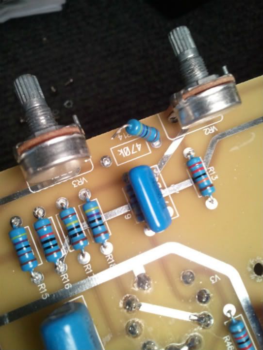
Step 1. Find R14 and lift the leg closest to VR3. You're basically installing the FX loop between the treble pot and the master volume pot.

Image
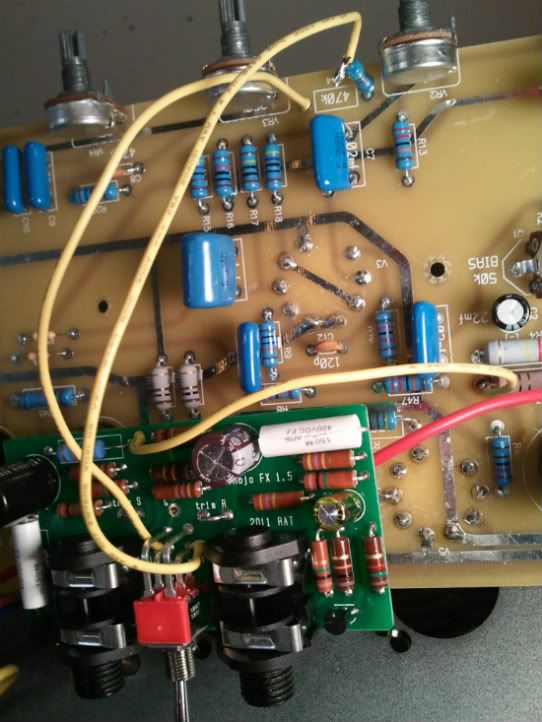
Step 2. On the FX loop's circuit board, you'll see a pad for "input". Solder a wire from this pad to the pad where R14 was pulled from back on the amp's board.

Step 3. On the FX loop's circuit board, you'll see a pad for "output". Solder a wire from this pad to the lifted leg of the amp's R14.

Image
Image
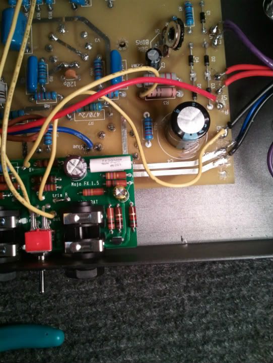
Step 4. On the FX loop's circuit board, locate the pad labeled "B+". Solder a wire from this pad to a leg of the amp's R3 resistor.

Image
Step 5. On the FX loop's circuit board, locate the pad labeled "G" for ground. Solder a wire from this pad to a grounding point on the amp's circuit board. I chose to go with the pad labeled "Ground" coming off of the power transformer.

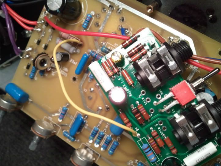
I won't bore you with instructions on drilling and mounting the card in the amp, but using Mojo's included template and a center punch to keep your holes centered will make the process much easier.

I tested the FX with a soundcard and IK's Guitar Rig. I opted to use my FX processor's level controls instead of wiring up send/return pots on the FX loop board. All seems to work just fine.

Post Reply