Moderator: VelvetGeorge


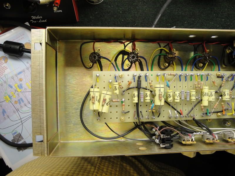
Great looking build Harddriver, I installed a shielding plate around the inputs and it seemed to help but there is still somthing not quite right. I will go back tonight and mess the wiring on the depth mod and also install some more shielded wires. Is that a second master (Jose) on your amp? I need to give that a try!!harddriver wrote:You may want to consider running shielded wire on all your input grids at V2a and V2B possibly V3A as well and maybe shielded wire on your depth mod. Try the shielded wire on your input grids, I didn't have any problem with my input jack being too close but I used the two furthest away from the preamp/volume controls on mine.
It sound like a presence/feedback circuit issue though, you may not want to drape the NFB wire over your power tube input grid wires like that, run it down the back of the chassis and tuck the other one closer to your power tube socket away from V4 PI preamp tube. I once tried putting three values of capacitors on a switch on my depth mod but I keep getting a high pitched oscillation ring with the switch installed, by all rights it should have worked. I ended up just using a single value cap, sounds great, NO RINGING!
Let us know how the troubleshooting goes!
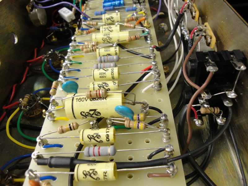
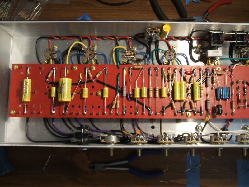
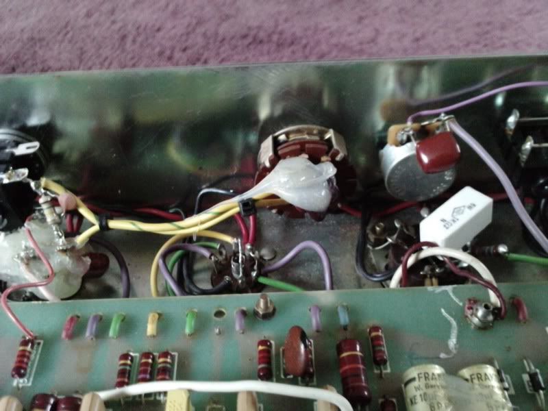
Check it out......harddriver wrote:I'm assuming that is a cathode resistor for V2B, what value is it, is it gray/red/red? 8200/8.2K?
What is the black wire with the resistor on the end doing running from the positive side of the V2B cathode resistor? Is it running to ground? It looks like it?
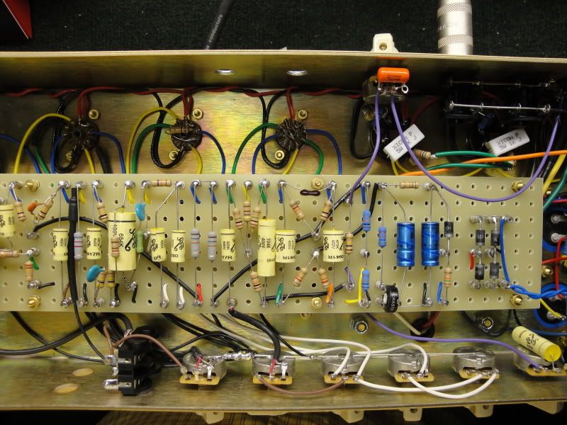
No offense Steve, the actual diagram is correct so I made a bad choice of works, what I meant is that it was not very effective. I tried putting it on the selector switch with the same results. On my own SLO it's wired like your diagram but, the twisted wires go directly to the board were one wire hooks up to the NFB resistor and another got to a Cap----see photo belowSDM wrote:
The resonance mod on my site is just a "generic" resonance control, like Soldano and Peavey use. Can be inserted before or after the NFB resistor. Works off of NFB like a presence control does, but for low end frequencies. Lower amount of NFB to start with means lower effect, same as with a presence control. Looks like you have (or had rather) it set up on the 4 ohm tap with a 100K NFB resistor, as low as anyone usually goes with Marshall 100 watters regarding NFB. So it's not going to have as much overall range/effect as it would if it was on a higher impedance tap and/or used in combination with a lower NFB resistor (which is how amps that have resonance controls from the get go are usually set up). Cap value has impact too on which frequencies the resonance control effects. As it states on my site, between .0022uf-.0047uf are the most commonly used values, but preferences may lie outside that range.
So you may have wanted to try using say the 8 ohm tap, then try a 47K-56K NFB resistor for starters on a getting a stronger effect. Maybe a .0022uf cap or such instead of .0047uf as that would extend the range of effected frequencies up higher in the mids. No notable change in control effectiveness, check your pot/pot value, cap/cap value (be sure you didn't use a .047uf or such), connections.
Perhaps similar changes are what you ultimately did comparing to the Cameron control? The basic resonance control will effectively defeat all low end NFB from the NFB loop (when cranked), thus allowing those lower frequencies to pass through the power amp full bore for a low end "boost". So, with all low end NFB already defeated/weeded out of the NFB loop, another version of a traditional style NFB based resonance control cannot add further low end "boost", only appear to do so by either making the control range more broad compared to other frequencies, and/or by extending the effected frequencies up higher via changing the cap value. Again though, the actual low end maximum itself is unaffected by these changes, but the control becomes much more effective overall. Low end boost effect will be stronger, but only relatively so - compared to the mids and highs now (which are now simply further damped down by more NFB in the NFB loop). This is usually the desired effect though, so works for many. This is just what the stuff in the paragraph above would do/does vs. how you originally had things set up. There are some other minor things that can be done, interactions to consider when tweaking, but the general idea on tweaking this kind of NFB resonance control is in the above.
Any way, if there is an actual error on the drawing, some inaccuracy or omission I am missing here regarding this, please let me know. Otherwise, the control (as depicted on the site) may just need some fine tuning around it or cap value tweaking to get the effect you want in a given amp. Still not enough for you, an active resonance boost may be a better approach (but is more difficult to implement).
I knew someone would catch thatharddriver wrote:Cool!I'm glad you got it all sorted out! I love the RED standby switch BTW, Did you think that detail would get past us here at METRO!