Info for maintaining and tweaking your amp to perfection.
Moderator: VelvetGeorge
-
neikeel
- Senior Member
- Posts: 7231
- Joined: Tue Dec 06, 2005 8:31 am
- Location: Suffolk, England
Post
by neikeel » Tue Nov 10, 2015 3:00 pm
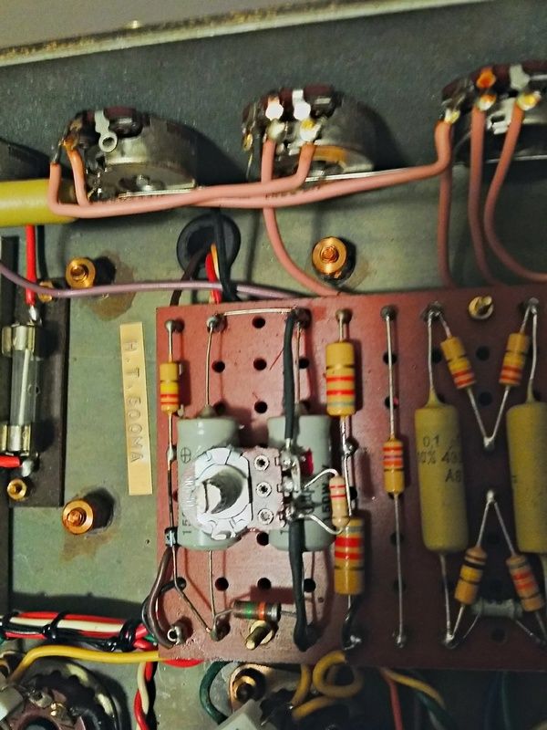
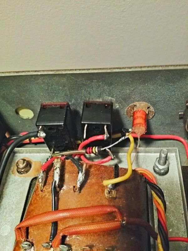
bahady30 wrote:Oke, thanks but I think I don't get it sorry. I thought the resistor has to be inserted after de rectifier diodes and not before if I read Larry's instructions correctly....my situation is that 2 red wires from the PT go to one site of standby switch . From the other side of the standby switch I see 2 blue wires go to the rectifier diodes. After the rectifier is the situation that I mentioned before. There is also one white wire that goes to the bias section. Where do I have to put my 100 K resistor now? Across which terminals of the standby switch should I solder my resistor? Thanks
If your amp is a later Marshall the standby is NOT the place for the resistor (the two ac feeds go to the standby and the ac then goes from the other two poles to the diodes). Early amps (and Georges clones switch rectified DC).
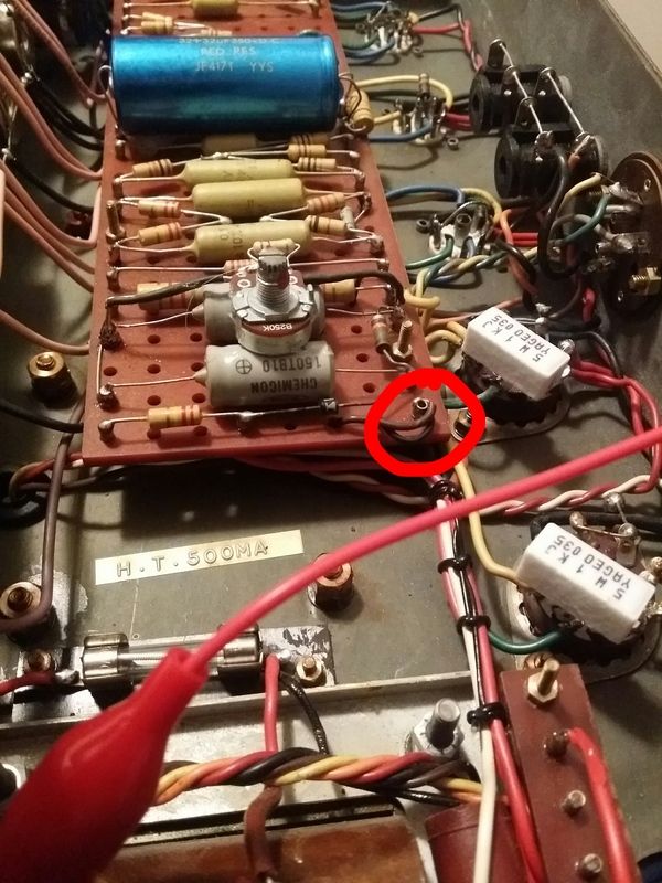
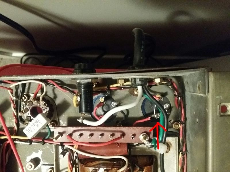
Insert the 100k after the diodes between red wire and the fuse holder tip, ideally solder and then follow instructions over probably only 3 or 4 hours with new F&Ts.
DON'T forget to bleed the caps before deoldering and reconnecting!!!

Neil
-
bahady30
- New Member
- Posts: 17
- Joined: Thu Oct 22, 2015 4:29 pm
- Just the numbers in order: 13492
Post
by bahady30 » Tue Nov 10, 2015 3:25 pm
Thanks man, that's what I want to hear. I appreciate this! Yes I will drain them . It's the first thing I always do when I'm gonna mess with my amp. Is it more safer to drain them through a resistor to ground to avoid sparks?
-
danman
- Senior Member
- Posts: 1099
- Joined: Tue Sep 10, 2013 9:09 pm
- Just the numbers in order: 13492
Post
by danman » Tue Nov 10, 2015 5:18 pm
Thanks for catching that Neikeel!

I should have checked his schematic before assuming the power supply was the same used in the older amps.
-
bahady30
- New Member
- Posts: 17
- Joined: Thu Oct 22, 2015 4:29 pm
- Just the numbers in order: 13492
Post
by bahady30 » Wed Nov 11, 2015 1:42 am
Thanks guys for clearing this up. Last question: Do I have to attach a speaker or dummy load when forming these caps? Thanks
-
neikeel
- Senior Member
- Posts: 7231
- Joined: Tue Dec 06, 2005 8:31 am
- Location: Suffolk, England
Post
by neikeel » Wed Nov 11, 2015 2:17 am
No - you have no tubes in, so no need (make sure the yellow wire is down stream of the resistor or your mains cans will not reform
Neil
-
bahady30
- New Member
- Posts: 17
- Joined: Thu Oct 22, 2015 4:29 pm
- Just the numbers in order: 13492
Post
by bahady30 » Fri Nov 13, 2015 4:18 am
Thanks for the help! I soldered the resistor in and fired the amp up. After 45 min I measured 3,3 VDC across the resistor so it's doing well I think. I let it sit for a while maybe the voltage will drop another 1V or so. Then drain the new caps, remove the resistor and put the new tubes back in. Maybe I hear some difference but that's not that important because the old Daly's were still good. I changed them because I want a reliable amp when gigging. I let you know how it sounds.

-
neikeel
- Senior Member
- Posts: 7231
- Joined: Tue Dec 06, 2005 8:31 am
- Location: Suffolk, England
Post
by neikeel » Sat Nov 14, 2015 4:04 am
bahady30 wrote:Thanks for the help! I soldered the resistor in and fired the amp up. After 45 min I measured 3,3 VDC across the resistor so it's doing well I think. I let it sit for a while maybe the voltage will drop another 1V or so. Then drain the new caps, remove the resistor and put the new tubes back in. Maybe I hear some difference but that's not that important because the old Daly's were still good. I changed them because I want a reliable amp when gigging. I let you know how it sounds.


Neil
-
bahady30
- New Member
- Posts: 17
- Joined: Thu Oct 22, 2015 4:29 pm
- Just the numbers in order: 13492
Post
by bahady30 » Sun Nov 15, 2015 5:59 am
Yesterday I had a gig in a large pub and I wanted to test the JMP at decent volume. After the cap job, new pre and output tubes, adding screen grid resistors , cleaning all of the electronics, I noticed the real potential of this amp. There is no hum or his or popping anymore, she is punchier, and has one of the fattest overdrive I heard from a combo. She's freakin loud, I couldn't get the master above 3 with our punk rock band and we are playing loud. Maybe she's a bit to bright because I couldn't turn up the treble above 1...I'm gonna experiment with the bright cap or clip it. Thank you all for your advice!!

-
Amp Healer
- New Member
- Posts: 4
- Joined: Mon Oct 17, 2011 2:45 pm
- Just the numbers in order: 7
- Location: Sweden
-
Contact:
Post
by Amp Healer » Fri Nov 20, 2015 8:05 pm
bahady30 wrote:Yesterday I had a gig in a large pub and I wanted to test the JMP at decent volume. After the cap job, new pre and output tubes, adding screen grid resistors , cleaning all of the electronics, I noticed the real potential of this amp. There is no hum or his or popping anymore, she is punchier, and has one of the fattest overdrive I heard from a combo. She's freakin loud, I couldn't get the master above 3 with our punk rock band and we are playing loud. Maybe she's a bit to bright because I couldn't turn up the treble above 1...I'm gonna experiment with the bright cap or clip it. Thank you all for your advice!!

Well don't know that amp u have ?
Saying JMP is saying I have a Volvo and not the model

But I guess u have a 2203 as u mention a master .
Install a cut kontroll an promise u will like it

-
bahady30
- New Member
- Posts: 17
- Joined: Thu Oct 22, 2015 4:29 pm
- Just the numbers in order: 13492
Post
by bahady30 » Sat Nov 21, 2015 4:39 am
It's a Marshall JMP 2104 from 1980 .
-
danman
- Senior Member
- Posts: 1099
- Joined: Tue Sep 10, 2013 9:09 pm
- Just the numbers in order: 13492
Post
by danman » Sat Nov 21, 2015 9:51 am
Try a couple of RFT ECC83's in it first. If they don't knock enough treble off then you can experiment with bright cap and treble peaker circuit.
-
Zentner
- New Member
- Posts: 1
- Joined: Wed Dec 09, 2015 9:50 pm
- Just the numbers in order: 13492
Post
by Zentner » Tue Dec 22, 2015 12:20 pm
-
coldengray
- Senior Member
- Posts: 186
- Joined: Mon Jun 24, 2013 3:39 pm
- Just the numbers in order: 13492
Post
by coldengray » Tue Feb 14, 2017 11:26 pm
I have scored a huge stash of old 50-50 and 8uf cap cans, among many other values. How can I reform them out of an amp? I do have a spare 50W PT if that will be useful. Also have a variac.
-
novosibir
- Senior Member
- Posts: 4654
- Joined: Tue Nov 22, 2005 2:32 pm
- Just the numbers in order: 7
- Location: Nuernberg, Germany
-
Contact:
Post
by novosibir » Tue Feb 14, 2017 11:52 pm
You don't need a variac.
Take four diodes 1N4007 or UF4007 and build a rectifier of it and hook up your electrolytics all in parallel, check for their rated voltages, so that they won't be exceeded. Swap in a resistor between rectifier positive and electrolytics positive. A 100K is ok for a total capacitance of 150...250uF
If your total capacitance is bigger, then go smaller with the resistor's value accordingly.
And yes - don't touch anything during the forming process, close the room and keep kids & cats outside the room

Larry
-
coldengray
- Senior Member
- Posts: 186
- Joined: Mon Jun 24, 2013 3:39 pm
- Just the numbers in order: 13492
Post
by coldengray » Wed Feb 15, 2017 12:32 pm
Thanks Larry
I found this elsewhere on the forum, does this match what you're saying? I'm doing this outside of an amp so what's the best way to apply AC voltage?


