Hello again everyone ...
as Tek said we've been doing some cool work lately
here's an update ...
the last version of the single channel CTP circuit saw me attempting to do the
triple-channel mixing through PWM controlled Gate resistances
causing "stepping" noise to ride along with the mixing mechanism
... which otherwise worked fine !
recall this was simply an alternative to the optical version,
which required matched cells to operate properly
I did this to see if I could match the overall behavior
and do away with the problems involved in opto-cell matching ...
(similar hassle as dealing w jFET's)
for that reason alone the idea of using switched analogue (bi-directional) gates is tempting
because matching is now built into the IC by design (with four gates per CD4066 chip)
part of the problem lies in the fact that there is no theory on this stuff
switched capacitor circuits are commonly studied
but not switched resistance
even though MXR used the idea in their Envelope Filter in the 70's
I know of no audio DIY who's done any theory or basic experimentation on the subject
I felt it was something I should do, and now could with tek's help ...
heck, I needed those answers for myself anyway
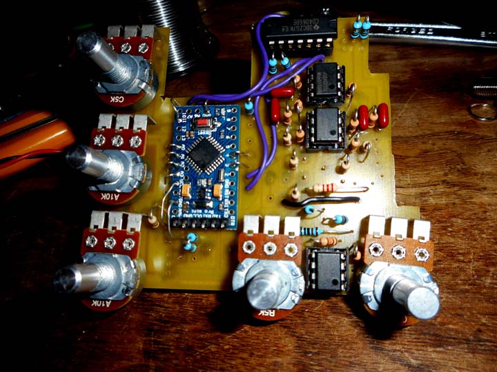
so, I got Tek to write me some new code
what we did was knock a couple of birds with one stone
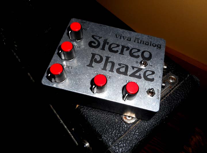
by designing a stereo phasor based on a well known approach
ie., using two Phase-45 circuits side by side running in opposite phase
the idea in the end is to have two perfectly sounding and identically behaving channels
I've come pretty close using my optical matching techniques, but it's never perfect
http://www.lynx.net/~jc/pwm01.jpg
http://www.lynx.net/~jc/pwm02.jpg
http://www.lynx.net/~jc/pwm03.jpg
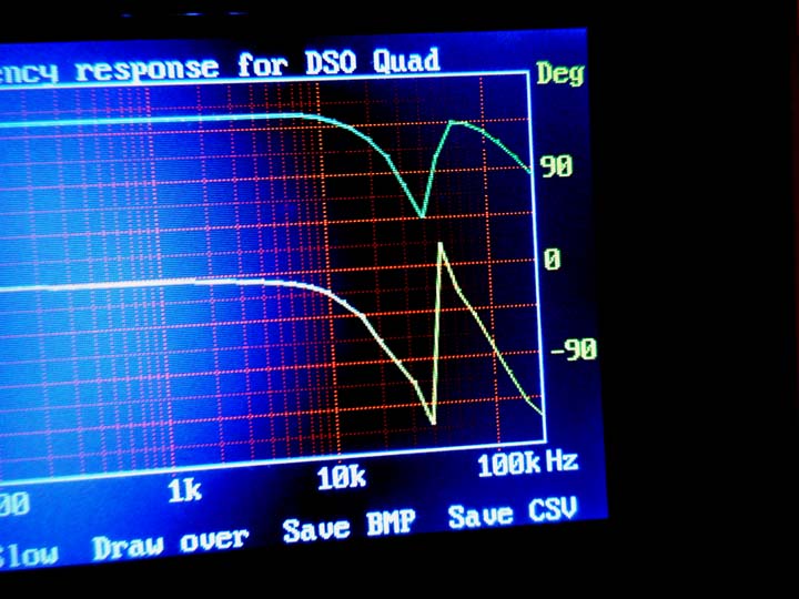
since op-amp based all-pass filters (what P45//P90 phasors are made of)
have a very predictable Bode response, that is,
Magnitude and Phase response versus frequency
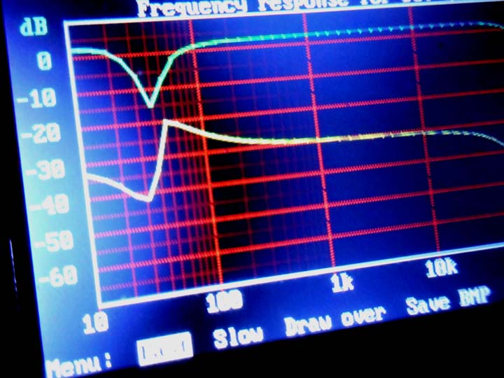
I could use my DSO-QUAD in spectrum analyzer mode to infer the equivalent resistance
by seeing where the characteristic notch lands
we did this by programing an Arduino Pro-Mini board to spit
out a minimum duty cycle of 0.39% ... ie., 1/256 ... at 32khz
in doing so I was able to play with the OFFSET control
and manually set the dutycycle to verify static operation first
this comes in handy later when I try to "avoid" a certain range if needed
this is similar to the external BIAS control in my P45 mods
which I refer to as a "COLOUR" control ... same deal here w OFFSET on the PWM
by going to the maximum 100% and minimum 0.39% statically
I was able to create a notch at 40khz and 40hz, respectively ...
http://www.lynx.net/~jc/pwm04.jpg
http://www.lynx.net/~jc/pwm05.jpg
since the phasor cap value is 0.01uF in this test
and we know the notch occurs where the equivalent resistance of the switched gate
is equal to the reactance of the capacitor
we can infer Requiv by using the following equation:
Requiv = 1/2piFC
which leads to 400 ohms (at 40khz) and 400k ohms (at 40hz)
showing that a 1000:1 resistance ratio is possible in an 8-bit setting
which is very much in line with several optical methods I used with NSL32-SR3 Silonex cells,
see here for details:
http://www.lynx.net/~jc/NSL32-SR3modeling.html
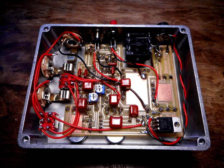
in the process of building my Stereo Phaze prototype I was discovered that the CD4066
is not the best choice for the job since it has a topology that leads to increased clock feedthrough
I just noticed that yesterday
by switching to the simpler CD4016 bi-directional switch IC I was able to do away
with the noise and generate a full-range stereo phasor operating cleanly ...
almost flawless behavior, as good if not better than using optical means
so - it's a milestone for me (maybe for the DIY community)
further tests and variations need to be made to see if I can go beyond the 0-5volt
environment and use the idea in high voltage settings
a PWM'd-gate Univibe is in the works as I'm always into checking out
alternative ways of making the Vibe happen ...
my opto-Vibe for example is all current-mode and operates using matched opto-couplers
this will make a radical alternative as well
as far as applicability to the present CTP research project
first thing will be to open up the PWM version (shown above)
and swap the 4066 IC for a 4016 and see if I get disappearance of noise
I spoke about there ...
and thus yield a better behaving mixing function ...
the only thing that might bite me there is a slewing issue with the comparator circuit
I'm using to convert Arduino 0-5v pulses to -7.5v/+7.5v ...
we'll see
recall, the optical version doesn't have that problem
so, if I'm successful it means that component matching will be done away here
and will make it much easier to build a full deal 4~5 channel CTP circuit ...
I don't care how big the sucker gets in the end
the cell-matching was really the strongest constraint holding me back
you never know, I might be able to pull this off at some point this winter
depending on resources, etc ...
that's it ... in principle this project is still alive
I wish I could solicit help with funds but it looks like I'm on my own as far as development costs go
so, for now it's matter of how much stuff I can sell at my store, how many amps come in for surgery, etc ...
which is starting to happen again, now that word's out locally
http://www.viva-analog.com
hope you're feeling better Dave
thx for watching // best regards, ...
~jcm

