Page 1 of 5
JTM 45/100 67 EL34
Posted: Sat Mar 17, 2012 4:23 am
by Homebelly
I would very much appreciate if some one could take a look at this layout and tell me where i need to connect both of the points marked with a question mark.
There is one running off of the mains plug and also one down by the HT fuse.
Thanks...

[edit-photo removed and replaced, see further down the thread-]
Re: Help with my JTM100 1203-80 layout
Posted: Sat Mar 17, 2012 6:04 am
by Roe
wire up 240v and common. don't fuse the neutral and wire the HT like the later superleads, not like the kt66 amps
btw this is 1967 circuit, not a 66 circuit
Re: Help with my JTM100 1203-80 layout
Posted: Sat Mar 17, 2012 8:06 am
by neikeel
Depends on how original style you want to go. Old style or modern (safer

)?
This is the basic schematic:
http://www.drtube.com/schematics/marshall/100w-67.gif
But you have to look at where the rectifier bridge is and draw another one below it (where the diagram lines have been extended).
For modern safety it is correct to wire such that live->mains fuse ->power switch in that order this then goes to the input selector
The neutral wire should not be switched or fused, but simply wired directly to the common mains lug on your PT primary which in your diagram means hooking the purple wire to the common lug on your PT primary.
Even safer would be to use a double pole mains switch, and have one side switching live and the other switching neutral.
Sorted!
Next is your HT. You have the tip of your HT to earth in the sketch which is clearly wrong.
Two ways of wiring your HT. First have your HT from the secondary pair to the rectifier which is then wired to the mains filter caps, you then switch that wire to the rest of the amp (OT primary centre tap/choke and B+ line to rest of amp. In this scenario lots of juice across that switch as the mains cans will be fully charged by the time you flip standby on.
Later way is to take the PT secondary wires from the PT to the standby switch (unrectified) and then take the cold side of these wires to the rectifier like this
http://www.drtube.com/schematics/marshall/1959spwm.gif
Re: Help with my JTM100 1203-80 layout
Posted: Sat Mar 17, 2012 2:05 pm
by Homebelly
Hi neikeel.
Thanks for the reply.
Before i ask a bunch more questions i would like to look at the schem's you have linked to, but the links don't seem to be working.

Re: Help with my JTM100 1203-80 layout
Posted: Sat Mar 17, 2012 5:21 pm
by Homebelly
Roe wrote:wire up 240v and common. don't fuse the neutral and wire the HT like the later superleads, not like the kt66 amps
btw this is 1967 circuit, not a 66 circuit
Oops.. my bad..
Thats what you get when you start recycling old templates in word and forget to change everything.
Re: Help with my JTM100 1203-80 layout
Posted: Sat Mar 17, 2012 5:22 pm
by Homebelly
Hi neikeel.
I found both schem's using wayback machine..
Cheers.
Re: Help with my JTM100 1203-80 layout
Posted: Sat Mar 17, 2012 5:46 pm
by Homebelly
neikeel wrote:
For modern safety it is correct to wire such that live->mains fuse ->power switch in that order this then goes to the input selector
The neutral wire should not be switched or fused, but simply wired directly to the common mains lug on your PT primary which in your diagram means hooking the purple wire to the common lug on your PT primary.
So.. Mr. neikeel... more like this?
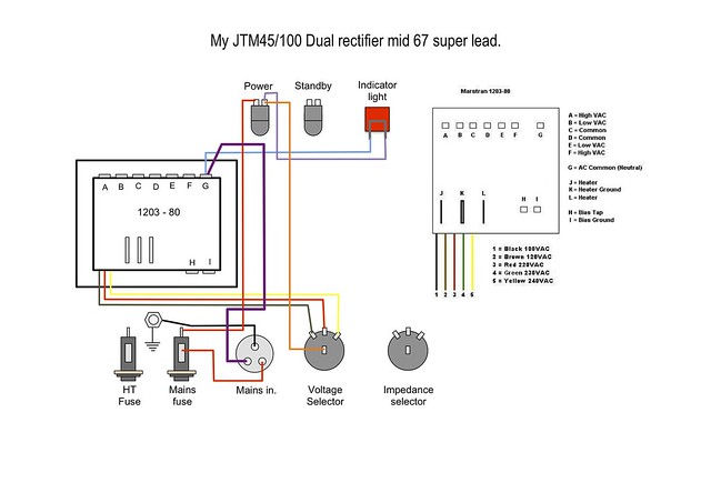
Also, does every thing else in the sketch look correct?
Re: Help with my JTM100 1203-80 layout
Posted: Sun Mar 18, 2012 8:20 am
by Roe
the indicator light should be 120v or 6.3v normally. isn't your wall voltage 240v?
Re: Help with my JTM100 1203-80 layout
Posted: Sun Mar 18, 2012 11:34 am
by neikeel
Yes that looks just right to me

Roe wrote:the indicator light should be 120v or 6.3v normally. isn't your wall voltage 240v?
True. I usually use a 6.3v off the heaters.
Homebelly are you happy about the HT arrangement?
Re: Help with my JTM100 1203-80 layout
Posted: Sun Mar 18, 2012 2:26 pm
by Homebelly
neikeel wrote:Yes that looks just right to me
Roe wrote:the indicator light should be 120v or 6.3v normally. isn't your wall voltage 240v?
True. I usually use a 6.3v off the heaters.
Homebelly are you happy about the HT arrangement?
RE; HT arrangement.
I haven't gotten to that part yet in my "building the amp on paper" project.
I'm still trying to work out how to connect the 1203-80 to the filter and rectifier board.
I have the dual rec' worked out, but the filter cans started doing my head in last night so i shelved it for the night.
I have a bunch of pictures from various places around the net, including some that Kevin sent me, of 1203-80 powered 67' amps and its a case of looking at them all and trying to figure it all out. The problem is, no one seems to follow the same wire color code
not that i expect them to, but wouldn't life be sweet if we all did.
I should have another drawing ready tonight or tomorrow.
Stay tuned... all feed back is welcome and needed.
Cheers.
Re: Help with my JTM100 1203-80 layout
Posted: Sun Mar 18, 2012 2:30 pm
by Homebelly
Roe wrote:the indicator light should be 120v or 6.3v normally. isn't your wall voltage 240v?
Yes.. 240 here.
I'll swap it over to the heaters as per neikeel's suggestion.
I was going to do this any ways as it seems to be the popular way to hook them up in the pictures i have of other amps.
I just over looked it in this drawing.
[edited to add fixed drawing]
 Power Transformer
 by
Homebelly, on Flickr
Re: Help with my JTM100 1203-80 layout
Posted: Sun Mar 18, 2012 5:48 pm
by neikeel
Here is my original dual rectifier amp:
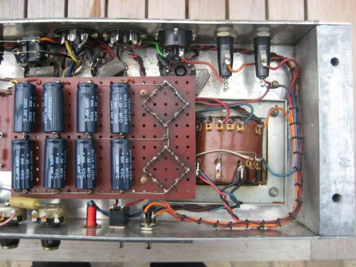
Not that you should be wiring it like that in these health and safety aware times
Re: Help with my JTM100 1203-80 layout
Posted: Mon Mar 19, 2012 9:56 pm
by Homebelly
Hi neikeel.
Thanks for the picture... I think i already have that one, and a whole lot of others, from you that i have harvested from arround the forum.
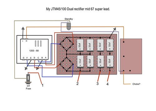
Here is my first stab at the bias, filter, rectifier and stand by switch.
Can you all take a look and tell me if i have done anything wrong.
I would also apreciate any hints as to where the connections marked 1, 2, 3, and 4 go.
I've tried in larging all of the photo's i have, and also checking them next to the schems i have that neikeel linked to and i'm getting no love.
I think after this round of questions i'll be able to figure the rest out and i can stop asking silly questions.
 Rectifier and filter board.
 by
Homebelly, on Flickr
Re: Help with my JTM100 1203-80 layout
Posted: Tue Mar 20, 2012 4:20 am
by Roe
isn't it rectifier->mains caps-> standby?
Re: Help with my JTM100 1203-80 layout
Posted: Tue Mar 20, 2012 2:29 pm
by Homebelly
Roe wrote:isn't it rectifier->mains caps-> standby?
So are you suggesting that Where i have the purple connection going to the choke, i should in fact have it going to where i have the #2 ?
My guess for the #2 connection was that it connected to the B+ at the bias point on the preamp/PI board where i have the orange connection going from "H" the bias tap from the PT.