First off, read these threads which will explain the principles involved:
http://forum.metroamp.com/viewtopic.php?f=4&t=25351" onclick="window.open(this.href);return false;
http://forum.metroamp.com/viewtopic.php?f=4&t=25351" onclick="window.open(this.href);return false;
Plus this site, which gives some nice technical insight:
http://www.aikenamps.com/StarGround.html" onclick="window.open(this.href);return false;
With this layout, you do not need to install a ground buss on the pots; neither soldered to the back of the pots, or suspended above the pots and attached to the grounded pot lugs. I think this is a major plus in itself; if you get trouble with one single pot, you can very easily replace just that one pot without desoldering the ground buss.
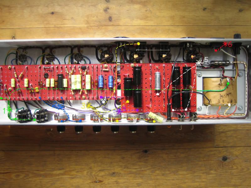
Similarly, you do not install a ground buss on the filter cap board. Only the two pairs of mains filter caps (the four caps all the way to the right on the below photo) are parallelled with a buss connection underneath the board. All the other ground points in the amp have their own ground wire run to one of 6 grounding points:
1: inputs, V1 cathode, heater center tap
2: volume pots, V2 cathode, preamp filter cap (if you use a 32+32 cap, you can alternatively run this to #3)
3: middle pot, presence pot, phase inverter filter cap, speaker jacks (OT secondary common is grounded to the speaker jacks in the usual manner)
4: bias capacitors, screen filter capacitors
5: rectifier snubber cap, mains filter caps, HT center tap (via fuse)
6: mains earth only
The power tube cathodes are run to ground via 1 ohm resistors to the adjacent tube socket lugs, so you can still do bias readings off of them. If you want to do this exactly by the book, you can run each of those ground points directly to #5.
Major thanks to Larry (novosibir) for walking me through this!