I finished this thing over the holiday:
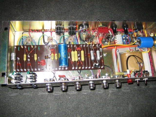
It's a bit of a hybrid spec 50-watter. Built with Marstran chassis and 1202-118 PT, M e r r e n 78-139 OT, Metroamp 352-114 choke, Sparky JTM black flag faceplate, Brian H board and Piher resistors like an early/mid-67 tube rectified black flag JTM50, i.e. Mustards, Lemcos and NOS Erie preamp filter cap, the other filter caps are F&T. Single 8.2k voltage dropper between screens and PI, 270k mixer resistors. Currently have negative feedback as 27k@8ohm, but might go with 16 ohm. I am still waiting for the rear faceplate, so will tidy up the rear panel connections when that arrives.
There are a few very rare amps with black flag faceplate but stock diode rectification, just as there are some JMP faceplate ones with tube rectifier. Typically those transitional amps had the single voltage dropper, 470k mix resistors and only 32uF mains, 32uF screens and 16uF PI filtering. Since I like the '68 spec JMP50s so much, I decided to make this amp switchable with some "in-between" values. Visually/aesthetically it's more of an early black flag style amp. In tube mode I have 32uF mains, 32uF screens, 32uF PI and 32+32uF preamp filtering. In diode mode I add another 32uF to the mains filtering for a total of 64uf. Late '67/early 68 ones sometimes had 48 or 50uF, later '68 ones crept up to 80uF or even 100uF. I chose 64uF since that was the easiest (dual 32) plus I wanted it to stick out from the tube mode a little more.
It sounds really nice and is very quiet, but does exhibit some "new amp stiffness" still, as I only have about 2-3 hours on it yet. We'll see how it fares with more burn-in, but I can't shake the feeling that those F&T caps just don't sound right in Marshall circuits. Anyone with me? I feel they're a bit grainy and stiff, not the right roundness to the tone. I just don't know which alternative might work better...
Anyway, here's a shot of how I wired the tube/diode switch. I used the 3PDT on/off/on switch that was used in the Metro dual voltage 12-series amps and is sold by Valvestorm. Two poles are used to switch the AC secondaries on the PT to either tube or diode rectifier. The third pole is used to switch in an extra 32uF in diode mode to the junction turret at the end of the board, where B+ comes from the standby switch via 32uF to meet with the OT CT and one choke wire.
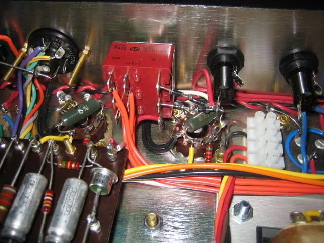
And now for the question: I hadn't counted on needing to adjust the bias for tube/SS mode individually. I thought the difference would be minor enough that it didn't matter (for the record, I get 420V with diodes and 410V with tube rectifier). However, my reflected bias reading (via the 1 ohm resistors) drops quite a lot in tube mode. If I have it at 45mA in diode mode (xf2 Mullards), it drops to 35mA in tube mode. Along with the lower plate voltage, it makes for a fairly cold bias in tube mode, and it sounds noticeably thinner. So I figure I need to put in some adjustment in tube mode. As I understand it, I should add some resistance to the raw bias feed (actually one half of the AC secondaries) in tube mode, is that correct?
Now the way I see I can do it on this switch, is to move the bias feed to the diode side of the switch, then put a resistor jumper between the center pole and the diode side. So when the switch is in diode mode, the bias circuit gets the full voltage. And in tube mode, the bias circuit draws through the resistor. Will that work?
The only problem I see is this: as the switch is now wired, it works like an alternate standby switch. I can switch from tube to diode mode without any problems, as the middle position is an "off" position where the AC secondaries get cut off from the rectifiers. I like this, as it means the tube rectifier only gets hit with HV AC when it's actually in use. The tubes remain biased regardless of the switch setting, as the bias feed is independent of the switch. However, if I were to wire it like I suggested above, the tubes would not be biased when the switch is in the middle position...or will they? I suppose they will still draw bias current via the resistor jumper...I'm getting confused. I want to avoid the problem that Marshall had in the early 70s, where the bias feed was on the far end of the standby switch, which meant that when the standby switch was thrown, the tubes were hit with full B+ before the bias circuit had charged up = massive current draw and burnt out PTs. As I understand it, this is the reason you see so many early 70s 50-watters with replaced PTs.
Anyway, does anyone see any problems with wiring it like I suggested?
