hi guys its done....
Im trying to figure out why the voltage on V1 Pin 3 is under 1volt.. just pulling it apart again to investigate..needless to say i did fire it up and it does work..no weird sounds or crazy stuff going on.....but the volume is low (im assuming it has to do with the above problem)
***still not getting full volume out of the amp, can have both vol knobs pinned and the amps doesn't break up and the mrs doesnt come running in to tell me to turn it down** **seems to be having a low voltage issue** any advise guys?
its done !!!
Moderator: VelvetGeorge
-
gibboau
- Senior Member
- Posts: 137
- Joined: Wed Jan 24, 2007 4:39 am
- Location: Australia
-
neikeel

- Senior Member
- Posts: 7231
- Joined: Tue Dec 06, 2005 8:31 am
- Location: Suffolk, England
Well done feels good doesn't it!
However, where are you losing the voltage?
At the top of the 10k/8k2 resistors you should have 420-440v (downstream of the choke where the OT screens come off and a filter cap). ie your B+ plate voltage.
If that is ok trace it across to the PI plate resistors should have 380v or so there.
Then the diagonal link to the other two 10k resistors each one should drop by 70v or so, such that at the junction of the two 100k V1 plate resistors you have 300v and about 190v without valves in.
To steal atip from SDM is the end lug on your presence pot hooked up to the earth bus wire on the back of the pots? If they are not the PI will not be earthed and not much juice will flow!
I guess more pics would be good.
ps I wish everyone would pull their wires through the board and wrap them round the turrets late 60's/early 70's style. Then you can see what is hooked up to what and not hidden under the board even if it looks prettier with them hidden, after all your link wires are on top.
I have not got xray vision like the pro trouble shooters
However, where are you losing the voltage?
At the top of the 10k/8k2 resistors you should have 420-440v (downstream of the choke where the OT screens come off and a filter cap). ie your B+ plate voltage.
If that is ok trace it across to the PI plate resistors should have 380v or so there.
Then the diagonal link to the other two 10k resistors each one should drop by 70v or so, such that at the junction of the two 100k V1 plate resistors you have 300v and about 190v without valves in.
To steal atip from SDM
I guess more pics would be good.
ps I wish everyone would pull their wires through the board and wrap them round the turrets late 60's/early 70's style. Then you can see what is hooked up to what and not hidden under the board
I have not got xray vision like the pro trouble shooters
Neil
-
gibboau
- Senior Member
- Posts: 137
- Joined: Wed Jan 24, 2007 4:39 am
- Location: Australia
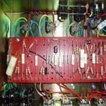
hey Neil thanks for the replay, here are some more pics
P3 of V1 is only reading 1Volt... this is driving me nuts
i have 429v at the top of the 10k 2w/8k2 2w resistors
sorry to be a newb but im not sure where the PI plate resistors are...??
at the junction of V1's 100k plate resistors im getting 417v...(without valves)
im using a bill batz layout with a split 16/16uf can for the pre amp filter (could this be the cause of the high voltage at V1's plate resistors?)
and the end lug of my presence pot hooked up to the earth bus wire on the back of the pots as well
Mike
-
neikeel
- Senior Member
- Posts: 7231
- Joined: Tue Dec 06, 2005 8:31 am
- Location: Suffolk, England
gibboau wrote:hey Neil thanks for the replay, here are some more pics
P3 of V1 is only reading 1Volt... this is driving me nuts
i have 429v at the top of the 10k 2w/8k2 2w resistors
sorry to be a newb but im not sure where the PI plate resistors are...??
These are the 82k and 100k resistors tied by the 47p cap
at the junction of V1's 100k plate resistors im getting 417v...(without valves)
If you have 400v at junction of the 100k resistors there is a problem with the resistor or the joint from which the blue wire goes to the valve base or there is a problem with the 0.022uF caps to your volume control (highly unlikely)
im using a bill batz layout with a split 16/16uf can for the pre amp filter (could this be the cause of the high voltage at V1's plate resistors?)
Not really as long as the cap is hooked up properly and the earth secured to the other earth point on the other filter cap lug and your dropping resitors are correct, voltages are ususally higher without valves in (5-10%)
and the end lug of my presence pot hooked up to the earth bus wire on the back of the pots as well
Good
Neil
-
gibboau
- Senior Member
- Posts: 137
- Joined: Wed Jan 24, 2007 4:39 am
- Location: Australia
-
gibboau
- Senior Member
- Posts: 137
- Joined: Wed Jan 24, 2007 4:39 am
- Location: Australia
ok guys, looks like i sorted the problem out..i rewired all the pre amp tubes and what do you know it seems to be working fine.....the volume is now strong enough to get the mrs running in telling me to turn it down... when you pin the volumes it produces what i would call the best sounding distortion ive ever heard.....
long live metro amps i say !!!!!!!!!
long live metro amps i say !!!!!!!!!
Mike
-
SDM
- Senior Member
- Posts: 1644
- Joined: Sun Feb 26, 2006 6:24 am
- Just the numbers in order: 13492
- Location: MI
You are running a split cathode setup on V1 in there right? So V1 pin 3 goes to the 820 ohm cathode resistor (and it's bypass cap)? If so, you should have around a volt (or a bit less typically) there on pin 3 if things are working/hooked up right. Not sure what you expected, but looks like you are all good there.
-Steve
Layout site
Layout site
-
gibboau
- Senior Member
- Posts: 137
- Joined: Wed Jan 24, 2007 4:39 am
- Location: Australia
hi Steve, yeah split cathode... i was expecting 1.8-2v on that pin (from the 50w voltage chart i found on the forum) needless to say the voltages on that chart didnt quite match the onces in my amp... (im assuming not all amps are created equally) im happy to report the amp rocks like no other ive owned.. it even makes my 94' twin amp sound "well" shit...
Mike
-
SDM
- Senior Member
- Posts: 1644
- Joined: Sun Feb 26, 2006 6:24 am
- Just the numbers in order: 13492
- Location: MI
Hey Mike, not sure what chart you were going by, but yeah many things can throw you off from any given voltage chart. For example the charted amp has a shared cathode V1, the V1 triodes are swapped around, just different cathode values used, altered/different circuit, higher/lower B+, the current the particular tubes draw themselves, recording errors, etc... 
Anyway congrats on the successful build!
Anyway congrats on the successful build!
-Steve
Layout site
Layout site
-
neikeel
- Senior Member
- Posts: 7231
- Joined: Tue Dec 06, 2005 8:31 am
- Location: Suffolk, England
-
gibboau
- Senior Member
- Posts: 137
- Joined: Wed Jan 24, 2007 4:39 am
- Location: Australia
hey guys,
here is the voltage chart : http://members.shaw.ca/house-of-jim/Html/Marshall.html
im just going to leave in a "as is" state and forget those voltages.. again there is no strange sounds or weird going ons
here is the voltage chart : http://members.shaw.ca/house-of-jim/Html/Marshall.html
im just going to leave in a "as is" state and forget those voltages.. again there is no strange sounds or weird going ons
Mike
-
Janglin_Jack

- Senior Member
- Posts: 640
- Joined: Thu Nov 23, 2006 11:16 am
I am certainly impressed with your wiring. Very neat, well done!! Good luck with the trouble shooting.
I know when I did my build, I checked, checked and re-checked all my wiring over and over. With the exception of the OT wires reversed on the power tube, (man did it squeal like a banshee). My fired right up.
Keep looking, you will find it!!
Jack
I know when I did my build, I checked, checked and re-checked all my wiring over and over. With the exception of the OT wires reversed on the power tube, (man did it squeal like a banshee). My fired right up.
Keep looking, you will find it!!
Jack
-
SDM
- Senior Member
- Posts: 1644
- Joined: Sun Feb 26, 2006 6:24 am
- Just the numbers in order: 13492
- Location: MI
I think you are all set, but just for the hell of it, drew up this chart of the ballpark voltages I would expect with your amp (430 V B+ and this version of the 1987 circuit taken into account). Did it kind of quick with no amp in hand, but hopefully it's pretty accurate.gibboau wrote: im just going to leave in a "as is" state and forget those voltages.. again there is no strange sounds or weird going ons
- Attachments
-
- 50wattervoltages.JPG (40.94 KiB) Viewed 876 times
-Steve
Layout site
Layout site