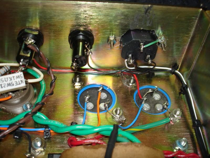
Cap arrangement looks fine to me.
I guess Chris has not got a 47k NFB resistor? (1/2 100=50)
Where are you running the NFB to?
Lead is usually 47k onto 8 ohm tap (later 100k onto 4ohm tap), really early models 27k onto 16ohm tap.
For a bass spec I would imagine 47k to a speaker jack rather than one of the impedence switch taps.
50 watt bass project!!!!
Moderator: VelvetGeorge
-
stokesdead
- Senior Member
- Posts: 254
- Joined: Fri Jun 16, 2006 11:18 pm
- Contact:
Right I didn't have a 47K resistor so I used 2 100K for a value of 50K but I have ordered some parts to finish up and that will be changed to a 47 K CC resistor. I have an extra wire coming off of the 8 ohm tap to connect to it but I could move it to a speaker jack if needed. BTW a question about the speaker jacks. George sent me the standard old style cliff jacks. Is it ok to use a shorting style jack for the speaker outputs?
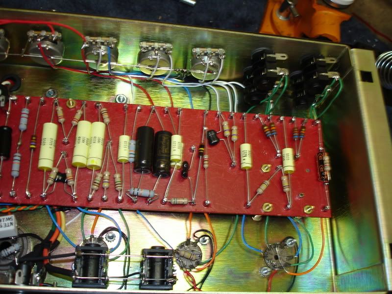
Not sure about the 10K resistors. I was following Rockstah's diagram. If that needs to be changed you guys know way more about it than me so let me know.
Thanks,
Chris Stokes
Not sure about the 10K resistors. I was following Rockstah's diagram. If that needs to be changed you guys know way more about it than me so let me know.
Thanks,
Chris Stokes
-
bluze81
- Senior Member
- Posts: 1403
- Joined: Tue Jun 27, 2006 8:36 am
- Just the numbers in order: 7
- Location: paradise mid america, los angeles CA native
If you were folowing rockstah"s layout then the 10k position is fine, I just never seen one quite like that layout but its a bass is why it looks different to me I am shure, not trying to throw you off on your build Chris,just needed to know its correct so it wont give you trouble when you fire it up, it looks good man. bluze
-
stokesdead
- Senior Member
- Posts: 254
- Joined: Fri Jun 16, 2006 11:18 pm
- Contact:
-
stokesdead
- Senior Member
- Posts: 254
- Joined: Fri Jun 16, 2006 11:18 pm
- Contact:
-
stokesdead
- Senior Member
- Posts: 254
- Joined: Fri Jun 16, 2006 11:18 pm
- Contact:
OK a few questions.
I have standard cliff shorting jacks on the speaker outputs. Is this correct?
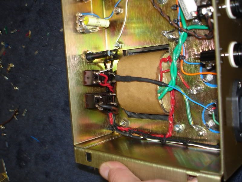
Is the PT wired up correctly? It is a part I would not want to replace.

Also the switches and all overall lead dress issues, any problems there?
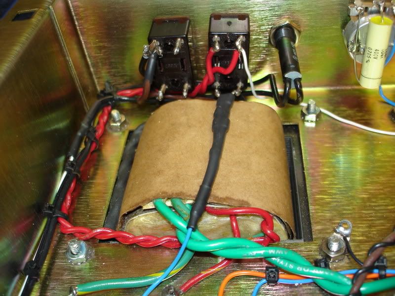
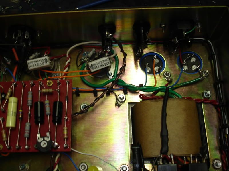
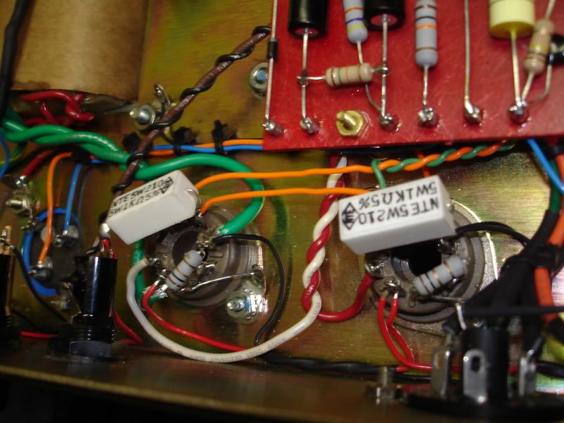
Please take a long hard look and if you guys need any more pics let me know. I am going to take a layout and a highlighter and double check all the connections. Wish me luck!
~Chris Stokes
I have standard cliff shorting jacks on the speaker outputs. Is this correct?
Is the PT wired up correctly? It is a part I would not want to replace.
Also the switches and all overall lead dress issues, any problems there?
Please take a long hard look and if you guys need any more pics let me know. I am going to take a layout and a highlighter and double check all the connections. Wish me luck!
~Chris Stokes
-
stokesdead
- Senior Member
- Posts: 254
- Joined: Fri Jun 16, 2006 11:18 pm
- Contact:
-
stokesdead
- Senior Member
- Posts: 254
- Joined: Fri Jun 16, 2006 11:18 pm
- Contact:
OK I fired her up!!!!!!
Heater voltage w/ no tubes installed: 3.25 VAC
I set the bias to get 34.1 mV on V4 and 35.1 on V5. Is this good? Are the readings close enough tolerance between the tubes?
If someone could direct me to a voltage chart. My meter does not have the auto-range feature. Just any ballpark numbers will help me take my readings.
First thing I notice is channel one has more noise. I plug a guitar into the input and it oscillates if I turn the volume all the way up. I would guess about 8 on the volume dial. Channel 1 also is kind of distorted. In a kinda cool way8) but I don't think it is right
Channel 2 sounds great! Really good I must say!!
If I can take some voltage readings, maybe I can figure out what part of the circuit has the problem.
Please let me know if you guys have any advice.
Thanks,
Chris Stokes
-
bluze81
- Senior Member
- Posts: 1403
- Joined: Tue Jun 27, 2006 8:36 am
- Just the numbers in order: 7
- Location: paradise mid america, los angeles CA native
Great Chris! the bias looks good for now but whats your plate volts reading? can you get that with the meter you are using? the distortion on ch,1 could be as easy as a bad solder joint, look at your inputs [solder joints]real good and check them with your meter for contanuity, and post current picture that way we can all take a look, Good job, bluze
-
stokesdead
- Senior Member
- Posts: 254
- Joined: Fri Jun 16, 2006 11:18 pm
- Contact:
OK here are my pin voltages. Plate seems high I thinks.
Valve position . pin #
1.1 - 165.7
1.3 - 1.36
1.6 - 153.8
1.8 1.37
2.1 - 143
2.3 - .97
2.6 - 262
2.7 - 142.3
2.8 - 144.5
3.1 - 198
3.3 - 33.3
3.6 - 200
3.8 - 33.4
4.3 - 423
4.4 - 420
4.5 - (-37.5)
5.3 - 423
5.4 - 420
5.5 - (-37.5)
What do you guys think?
~Chris Stokes
Valve position . pin #
1.1 - 165.7
1.3 - 1.36
1.6 - 153.8
1.8 1.37
2.1 - 143
2.3 - .97
2.6 - 262
2.7 - 142.3
2.8 - 144.5
3.1 - 198
3.3 - 33.3
3.6 - 200
3.8 - 33.4
4.3 - 423
4.4 - 420
4.5 - (-37.5)
5.3 - 423
5.4 - 420
5.5 - (-37.5)
What do you guys think?
~Chris Stokes
-
stokesdead
- Senior Member
- Posts: 254
- Joined: Fri Jun 16, 2006 11:18 pm
- Contact:
I noticed that the valve in V1 wasn't sitting in the socket well. Pulled it out looked like I got some solder in pins 6 & 7. I heated these up and cleaned them the best I could. It helped the osscilation some but the problem is still there just a little better. Should I replace that tube socket or should I look elsewhere for my problem?
~Chris Stokes
~Chris Stokes
-
neikeel

- Senior Member
- Posts: 7231
- Joined: Tue Dec 06, 2005 8:31 am
- Location: Suffolk, England
Voltages look good to me.
As always try some tubes that you know are quiet and work first of all, they do not have to sound particularly good.
Check the grounding on your inputs (I think Bluze touched on this). You have to look why this is only on channel 1 (sorry if it sounds obvious) particularly the earth bus on the back of ch 1 pot. Check the cap to ch1 was not toasted on installation.
As always try some tubes that you know are quiet and work first of all, they do not have to sound particularly good.
Check the grounding on your inputs (I think Bluze touched on this). You have to look why this is only on channel 1 (sorry if it sounds obvious) particularly the earth bus on the back of ch 1 pot. Check the cap to ch1 was not toasted
Neil
-
stokesdead
- Senior Member
- Posts: 254
- Joined: Fri Jun 16, 2006 11:18 pm
- Contact:
OK well tonight I am blowing HT fuses. I am using .5 A fast-blo the rating is 250V. Is this the problem? I am measuring 455V from the HT fuse to neutral on the IEC plug.
Besides this the oscillation has gotten tamer but is still there after I found some suspect solder joints and cleaned them up. The overall amp has a very bad tone though. It is very woofy. The bass is HUGE in comparison to the other frequencies. But the bass frequencies are very loose and overpowering. Also the higher notes have some harmonic overtones that aren't very pleasant. Could this be symptoms of under filtering the amp?
I wish I could post clips but I don't have a way to record.
~Chris Stokes
-
neikeel
- Senior Member
- Posts: 7231
- Joined: Tue Dec 06, 2005 8:31 am
- Location: Suffolk, England
Oh!
The voltage you measure is about correct that is the B+ people refer to, it is the plate voltage of your power tubes, on my metal panels it is around 400v and my metro 50watter about 440v (do you have the valves in when you measure?
Your filtering (as long as they are in spec. and not some dodgy 40 year old NOS caps) should not cause these problems. It is good that you checked and tidied all your joints.
I wonder how the preamp filter cap pairing is hooked up, without seeing where your power feed links are itis difficult. Check teh schematic such that the link from the 82k/100k tie point in the PI goes to the 10k 2watter and then to the filter cap, then to the 10k to teh other filter cap and then to pin6 of V2 in that order.
Neil